Advertisement
Quick Links
QS300480 Rev B
©2013 Flowline, Inc.
All Rights Reserved
Made in USA
EchoSonic® II
Ultrasonic Level Transmitter
LU23, LU28 & LU29 Series Quick Start
NEMA 4X Enclosure
Tel: 562.598.3015 • Fax: 562.431.8507 • www.flowline.com
10500 Humbolt Street, Los Alamitos, CA 90720 USA
1
Advertisement

Related Manuals for FlowLine EchoSonic II Series


Summary of Contents for FlowLine EchoSonic II Series
- Page 1 LU23, LU28 & LU29 Series Quick Start NEMA 4X Enclosure QS300480 Rev B ©2013 Flowline, Inc. All Rights Reserved 10500 Humbolt Street, Los Alamitos, CA 90720 USA Made in USA Tel: 562.598.3015 • Fax: 562.431.8507 • www.flowline.com 1 ...
- Page 2 The EchoSonic® II quick start is meant to show some of the more common setup solutions to getting the EchoSonic® II up and running quickly. If you run into an issue that is not addressed here or wish to install or set up with a non‐standard configuration, please address the EchoSonic® II Manual or refer to the Flowline website at www.flowline.com. We Do Your Level Best ...
- Page 3 Configuring the EchoSonic® II Configuration of your sensor should be performed prior to mounting, since it requires connection to your PC. Step 1: Install the WebCal™ Software Download WebCal™ from www.flowline.com onto a PC with the following minimum specifications: ® Windows 2000/XP/Vista/7/8, 10 MB storage space, 256 MB RAM, 1 USB 2.0 port Double‐click the WebCal™ icon to install before proceeding to Step 2. You must have an ...
- Page 4 Step 3: Configure through WebCal™ These instructions will walk you through configuration of the sensor through WebCal™. For more information, click the WebCal™ HELP button in the lower right corner or anywhere on the WebCal™ screen or refer to the EchoSonic® II manual found at www.flowline.com. WebCal™ Configuration Screen 4 ...
- Page 5 Using the drop‐down menus on the left of the WebCal™ screen set the configuration for your application requirements. When a selection does not apply to your application, “Not Applicable” will appear in the drop‐down. Make sure all drop‐downs are set appropriately for your application before moving to the Tank Level section. Loop Fail Safe. Use this setting to choose the output level should the sensor not receive an echo. Output at Empty. Use this setting to change the 4‐20 mA setting from its default. ...
- Page 6 Enter the appropriate tank level set points for your application. Units. Display measurements in inches or centimeters. Sensor Height. Distance measured from the bottom of the empty tank to the bottom of the transducer. Under factory configuration, this becomes the 4 mA set point. Fill Height. Distance measured from the bottom of the empty tank to the maximum fill height within the tank. Under ...
- Page 7 The Advanced button is used for options available when setting up the sensor with special, non‐standard features. Many of these features are available for specific applications that may change from time to time. Consult WebCal™'s HELP file for the latest information on the use of any of these features. The more commonly used Advanced features are the Invert Relay and Increase Output Filtering described below. Increase Output Filtering. Select this radio button to add additional filtering to the 4‐ 20 mA output. Decrease Output Filtering. Select this Advanced Settings radio button to remove all output filtering on the 4‐20 mA output. Before configuration can be completed: You must click the Write to Unit button to save the settings to the unit. Then, click Wiring Diagram for a hard copy of the sensor’s settings. Finally, enter the file name under which you wish to save the configuration file and click Save Config File. Configuration is now complete. Disconnect the USB Fob before continuing to the next step: Mounting the EchoSonic® II. For updates to WebCal™, or to make sure you’re using the most up‐to‐date version available, click the Update tab on the top of the WebCal™ screen. ...
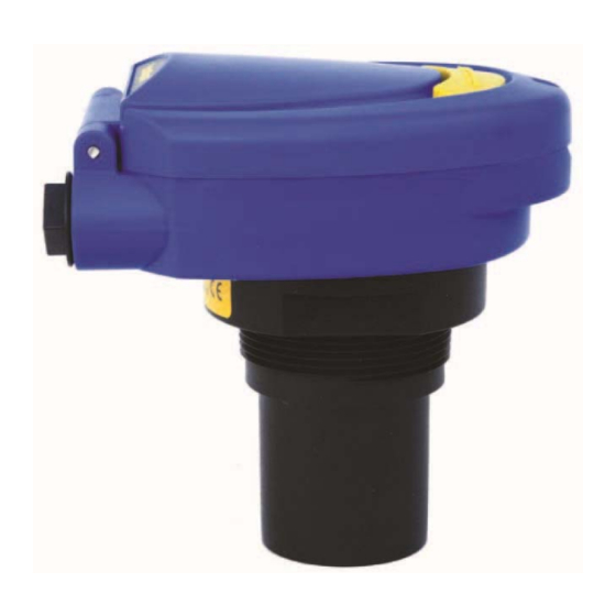
- Page 8 Mounting the EchoSonic® II The sensor should always be mounted perpendicular to the liquid surface using the provided Viton® mounting gasket. Insure that there are no restrictions or obstacles in the path of the ultrasonic signal. Further mounting information can be found on the Flowline website at www.flowline.com. Mounting with a Tank Adapter: Select a tank adapter fitting, such as the LM52‐2890. Mounting with a Riser: As installations with tall, narrow risers can impede the acoustic signal. 2" diameter risers should be no taller than 5". Larger diameter risers should be no taller than 12". Mounting with a Side Mount Bracket: Use Flowline's LM50‐1001 side mount bracket. ...
- Page 9 Mounting with a Stand‐Pipe: A stand‐pipe may be used to dampen turbulence, separate surface foam from the point of measurement or increase performance in heavy vapor. When mounting the sensor in a stand‐pipe, the minimum diameter of the pipe is 3”. Larger diameter pipes can be used. The pipe should be attached with a coupling and reducer bushing. The pipe length should run the measurement span and the bottom of the pipe should remain submerged at all times to prevent foam from entering the pipe. Cut the bottom end of the pipe at 45° and drill a 1/4”pressure ...
- Page 10 Wiring the EchoSonic® II After mounting the sensor, make the necessary electrical connections. A wiring diagram with specific recommendations for the sensor’s configuration can be printed from the WebCal™ program. A typical wiring diagram is shown on the next page. Red (+) & Black (‐): Red (R/+) and Black (BLK/‐) leads are for connection to a 24 VDC power supply or to a 4‐20 mA loop power source. The red and black wires can be extended up to 1,000 feet using a 22 gauge or larger wire; however do not extend the green and white wires. ...
- Page 11 Wiring the EchoSonic® II The following wiring diagram can be used when wiring to the EchoSonic® II relays. Typical Wiring Diagram Your WebCal™ Wiring Diagram may vary. General notes for electrical connections, usage and safety: Where personal safety or significant property damage can occur due to a spill, the installation must have a redundant backup safety system installed. Wiring should always be completed by a licensed electrician. Supply voltage should never exceed 28 VDC. Protect the sensor from excessive electrical spikes by isolating the power, whenever possible. The sensor materials must be chemically compatible with the liquids to be measured. Design a fail‐safe system for possible sensor and/or power failure. Never use the sensor in environments classified as Hazardous. ...
- Page 12 2) the product has remained unclaimed at Flowline for more than 30 days after Flowline has dutifully requested disposition. This warranty contains the sole express warranty made by Flowline in connection with its products. ALL IMPLIED WARRANTIES, INCLUDING WITHOUT LIMITATION, ...
Need help?
Do you have a question about the EchoSonic II Series and is the answer not in the manual?
Questions and answers