Advertisement
Quick Links
Echo
oSon
Ultrasonic Liq
quid Level Tran
LU
U23, LU28
8 & LU29
©20
19 Flowline,
Inc.
All R
Rights Reser
rved
Mad
e in USA
Flowlin
ne, Inc. | 10500 Hu
umbolt Street, Los
®
nic
nsmitter
Series Q
Quick Sta
Alamitos, CA 9072
20 p 562.598.3015
rt
5 f 562.431.8507
w flowline.com
QS300610 Rev D D 2
Advertisement

Related Manuals for FlowLine EchoSonic LU23 Series


Summary of Contents for FlowLine EchoSonic LU23 Series
- Page 1 Ultrasonic Liq quid Level Tran nsmitter U23, LU28 8 & LU29 Series Q Quick Sta ©20 19 Flowline, Inc. All R Rights Reser rved e in USA Flowlin ne, Inc. | 10500 Hu umbolt Street, Los Alamitos, CA 9072 20 p 562.598.3015...
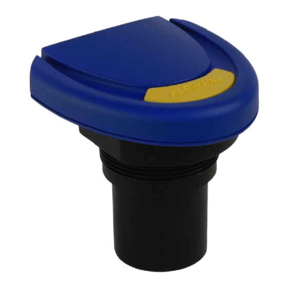
- Page 2 Flowline website at flowline.com. WE DO YOUR LEVEL BEST ® Thank you for purchasing Flowline’s EchoSonic . This general purpose ultrasonic sensor provides non- contact detection up to 32.8” (10 m) powered by the 4-20 mA loop. This quick start includes everything you’ll ®...
- Page 3 CONFIGURING THE ECHOSONIC Configuration of your sensor should be performed prior to mounting, since it requires connection to your PC. Step 1: Install the WebCal® Software Download WebCal® from flowline.com/webcal-software onto a PC with the following minimum specifications: ® Windows XP/Vista/7/8/10, 10 MB storage space, 256 MB RAM, 1 USB 2.0 port...
- Page 4 These instructions will walk you through configuration of the sensor through WebCal . For more information, ® ® click the WebCal HELP button in the lower right corner or anywhere on the WebCal screen or refer to the ® EchoSonic manual found at flowline.com. ® WebCal Configuration Screen QS300610 Rev D2...
- Page 5 ® Using the drop-down menus on the left of the WebCal screen set the configuration for your application requirements. When a selection does not apply to your application, “Not Applicable” will appear in the drop-down. Make sure all drop-downs are set appropriately for your application before moving to the Tank Level section.
- Page 6 Enter the appropriate tank level set points for your application. Units. Display measurements in inches or centimeters. Sensor Height. Distance measured from the bottom of the empty tank to the bottom of the transducer. Under factory configuration, this becomes the 4 mA set point.
- Page 7 The Advanced button is used for options available when setting up the sensor with special, non-standard features. Many of these features are available for specific applications that may change from time to time. ® Consult the HELP file in WebCal for the latest information on the use of any of these features.
- Page 8 Insure that there are no restrictions or obstacles in the path of the ultrasonic signal. Further mounting information can be found on the Flowline website at flowline.com. Mounting with a Tank Adapter Select a tank adapter fitting, such as the LM52-2890.
- Page 9 Mounting with a Stand-Pipe: A stand-pipe may be used to dampen turbulence, separate surface foam from the point of measurement or increase performance in heavy vapor. When mounting the sensor in a stand-pipe, the minimum diameter of the pipe is 3”. Larger diameter pipes can be used. The pipe should be attached with a coupling and reducer bushing.
- Page 10 ® WIRING THE ECHOSONIC After mounting the sensor, make the necessary electrical connections. A wiring diagram with specific ® recommendations for the sensor’s configuration can be printed from the WebCal program. A typical wiring diagram is shown on the next page. Red (Power) and Black (Return) leads are for connection to a 24 VDC power supply or to a 4-20 mA loop power source.
- Page 11 ® WIRING THE ECHOSONIC ® The following wiring diagram can be used when wiring to the EchoSonic Sample Wiring Diagram Diagram will change based upon the sensor’s configuration, use ® WebCal to view appropriate wiring diagram. ® Typical Wiring Diagram (Your WebCal Wiring Diagram May Vary) General notes for electrical connections, usage and safety ...
-
Page 12: Warranty
PERSON IS AUTHORIZED TO MAKE ANY OTHER WARRANTIES OR REPRESENTATIONS ON BEHALF OF FLOWLINE. This warranty will be interpreted pursuant to the laws of the State of California. If any portion of this warranty is held to be invalid or unenforceable for any reason, such finding will not invalidate any other provision of this warranty.
Need help?
Do you have a question about the EchoSonic LU23 Series and is the answer not in the manual?
Questions and answers