Table of Contents
Advertisement
Quick Links
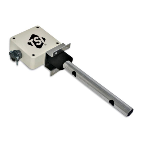
Figure 1. TF-Series Thermal Flow Station
TF-Series Flow Station Placement
The following paragraphs detail the procedure for determining optimum placement of the TF-Series Flow
Station in typical installation applications.
Installation of the TF-Series Flow Station with straight duct lengths equal to or greater than
indicated in the Minimum Placement Guidelines below is critical for proper performance of the
airflow measurement station.
Minimum Placement Guidelines
Placement of the TF-Series Flow Station is critical for proper operation and accuracy of the airflow
measurement station. Figure 2 shows minimum placement requirements for the TF-Series Flow Station in
typical applications. Probe placement is expressed in multiples of 'Simple Equivalent Duct Diameter – "D,"
which is determined as follows:
D = (duct width + duct height) / 2
1. Using the illustration in Figure 2 that most closely matches the installation, multiply the calculated "D"
value from above by the value indicated in the application illustration. This is the calculated location for the
TF-Series Flow Station.
2. Mark the duct location and install the TF-Series Flow Station at the calculated location.
_____________________
TSI and TSI logo are registered trademarks of TSI Incorporated.
INSTALLATION INSTRUCTIONS
WARNING
The Model TF-Series Flow Stations must be wired to
24 VAC only. Wiring the unit to 110 VAC will cause
serious damage to the unit and void the warranty.
CAUTION
MODEL TF-SERIES
FLOW STATION
Advertisement
Table of Contents

Related Manuals for TSI Instruments TF Series


Summary of Contents for TSI Instruments TF Series
- Page 1 MODEL TF-SERIES FLOW STATION INSTALLATION INSTRUCTIONS WARNING The Model TF-Series Flow Stations must be wired to 24 VAC only. Wiring the unit to 110 VAC will cause serious damage to the unit and void the warranty. Figure 1. TF-Series Thermal Flow Station TF-Series Flow Station Placement The following paragraphs detail the procedure for determining optimum placement of the TF-Series Flow Station in typical installation applications.
- Page 2 AFMS AFMS Airflow AFMS AFMS Airflow Airflow 0.75 D 0.75 D 1.5 D Unvaned Elbows Vaned Elbows AFMS AFMS Airflow Airflow 0.5 D 0.5 D 0.5 D 1.5 D AFMS Airflow AFMS AFMS Airflow AFMS 0.75 D 1.5 D Radius Elbows Transitions AFMS AFMS...
- Page 3 Rectangular Duct Placement Round Duct Placement ½ X ½ X ½ X ½ X Flat-Oval Duct Placement Across major axis Across minor axis ½ X ½ X ½ X ½ X Figure 3. TF-Series Installation Flow Station Applications and Orientation TF-Series Flow Station Installation The TF-Series Flow Station is designed for use indoors in ducts up to 16 inches and in VAV terminal box applications TF-Series airflow measurement station sensor probes are designed for insertion mounting...
- Page 4 3. Locate and mark the point on the duct or VAV box where the probe will be inserted using the previous Minimum Placement Guidelines section of this document. Refer to Figure 3 and Figure 4 for TF-Series Flow Station dimensions and probe orientation. 4.
- Page 5 TF-Series Analog Output Connections CAUTION 24 VAC power must be deactivated before making connections to the instrument. CAUTION The 24 VAC input ground (GND) connection is shared with the analog output signal ground. If an isolated output is desired, a dedicated isolation transformer is required to power the TF-Series Flow Station.
- Page 6 24 VAC + 24 VAC - RED (24 V+) BLACK (COMMON) WHITE (VEL +) TF- Series VEL AO - Flowstation Junction Box VEL AO + (By Others) 3-foot cable provided (pigtail connection) Color Function 24 VAC power Black Common TF-Series Flow Station Power/Signal Ground (for 24 VAC and for analog output) White Velocity Analog Output Signal...
- Page 7 TF-Series Flow Station Analog Output Option Switch Settings To access the field selectable analog output option switches, remove the four retaining screws at each corner of the TF-Series Flow Station enclosure cover. The option selector switches are part of a four-switch DIP package labeled CONFIG.
- Page 8 TF-Series Flow Station Initial Start Up / Normal Operation The following procedure is intended for initial start-up of the TF-Series Flow Station. Following the initial set up, no further user activity is required during normal operation. 1. Remove the cover to the electronics enclosure by removing the four screws on the cover. 2.
Need help?
Do you have a question about the TF Series and is the answer not in the manual?
Questions and answers