
Subscribe to Our Youtube Channel
Related Manuals for TSI Instruments Airflow TA500 Series


Summary of Contents for TSI Instruments Airflow TA500 Series
- Page 1 ™ Airflow Instruments Air Velocity Meter Model TA500 Series Operation and Service Manual P/N 6016532, Revision A August 2022 www.tsi.com...
- Page 2 Start Seeing the Benefits of Registering Today! ® ® Thank you for your TSI instrument purchase. Occasionally, TSI releases information on software updates, product enhancements and ® new products. By registering your instrument, TSI will be able to send this important information to you. http://register.tsi.com As part of the registration process, you will be asked for your comments on TSI products and services.
-
Page 3: Warranty
Warranty Copyright TSI Incorporated / 2022 / All rights reserved. Address TSI Incorporated / 500 Cardigan Road / Shoreview, MN 55126 / USA Fax No. 651-490-3824 E-mail Address answers@tsi.com Limitation of Warranty (For country-specific terms and conditions outside of the USA, please visit and Liability www.tsi.com.) (effective February 2015) - Page 4 TO THE EXTENT PERMITTED BY LAW, THE EXCLUSIVE REMEDY OF THE USER OR BUYER, AND THE LIMIT OF SELLER'S LIABILITY FOR ANY AND ALL LOSSES, INJURIES, OR DAMAGES CONCERNING THE GOODS (INCLUDING CLAIMS BASED ON CONTRACT, NEGLIGENCE, TORT, STRICT LIABILITY OR OTHERWISE) SHALL BE THE RETURN OF GOODS TO SELLER AND THE REFUND OF THE PURCHASE PRICE, OR, AT THE OPTION OF SELLER, THE REPAIR OR REPLACEMENT OF THE GOODS.
-
Page 5: Table Of Contents
Contents WARRANTY ..................III SAFETY .................... VII Description of Caution/Warning Symbols ........vii Caution ..................vii Warning ..................vii Caution and Warning Symbols ............viii Labels ..................... viii RoHS ....................ix CE ....................ix Reusing and Recycling ..............ix ® Bluetooth Safety and Compliance(TA550) ........ - Page 6 Assign Programmable Soft Keys ........... 18 Main Menu ..................19 Zero Pressure ................. 19 Settings................... 20 Flow Setup ..................20 Workflows ..................21 Logging Profile ................21 Manage Data .................. 22 CHAPTER 4 SETTINGS ..............23 Display Order ................. 23 Actual/Standard ................
-
Page 7: Safety
Safety This section provides instructions to ensure safe and proper operation of the Airflow™ Instruments Air Velocity Meter Series TA500. W A R N I N G S • The instrument must be used in the manner described in this manual. -
Page 8: Caution And Warning Symbols
C a u t i o n a n d W a r n i n g S y m b o l s The following symbols may accompany cautions and warnings to indicate the nature and consequences of hazards: Warns that uninsulated voltage within the instrument may have sufficient magnitude to cause electric shock. -
Page 9: Rohs
7. Example 8. Example European symbol for non- disposable item. Item must be recycled. R o H S Airflow™ Instruments TA500 Series instruments are RoHS compliant. Airflow™ Instruments TA500 Series instruments are CE compliant. R e u s i n g a n d R e c y c l i n g Incorporated’s effort to have a minimal negative ®... - Page 10 NOTICE This device may not cause interference; this device must accept any interference, including interference that may cause undesired operation of the device. l’appareil ne doit pas produire de brouillage; l’appareil doit accepter tout brouillage radioélectrique subi, même si le brouillage est susceptible d’en compromettre le fonctionnement.
-
Page 11: Chapter 1 Unpacking And Parts Identification
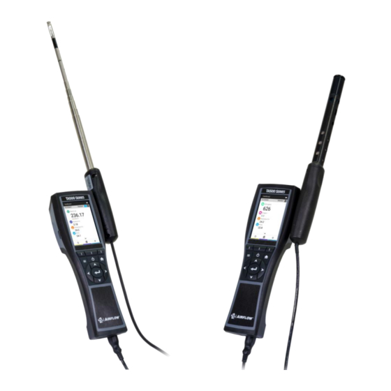
C H A P T E R 1 Unpacking and Parts Identification Carefully unpack the instrument and accessories from the shipping container. Check the individual parts against the list of components ® below. If anything is missing or damaged, notify TSI immediately. -
Page 12: Optional Plug In Probes
O p t i o n a l P l u g I n P r o b e s Telescopic Thermoanemometer Probes Model No. Description Air Velocity and Temperature, Straight Probe Air Velocity and Temperature, Articulating Probe Air Velocity, Temperature, and Humidity, Straight Probe Air Velocity, Temperature, and Humidity, Articulating Probe Telescopic Thermohygrometer Probe Model No. -
Page 13: Optional Accessories And Replacement Parts
Optional Accessories and Replacement Parts Part No. Description Picture 800122 AC/DC Adapter/Power Supply 802241 USB Thermal Printer ® 801190 Bluetooth Printer (TA550 only) 80211 Printer paper (5 rolls) 800681 IAQ probe stand 801748 Telescopic, articulated extension for 995 RV probe 372000000 8 ft. - Page 14 Part No. Description Picture 800130 Carrying case, small: Accommodates (1) meter and up to (2) probes (IAQ or thermoanemometer) Airflow™ Instruments Air Velocity Meter Model TA500 Series...
-
Page 15: Chapter 2 Setting Up The Airflow™ Instruments Meter
C H A P T E R 2 Setting Up the Airflow™ Instruments Meter P r o v i d i n g P o w e r t o t h e A i r f l o w ™ I n s t r u m e n t s M e t e r The Model TA500 Series Airflow™... -
Page 16: Case Magnets, Probe Holder And Wrist Strap
C A U T I O N ® Use only the approved AC/DC power supply (TSI part number ) and DO NOT substitute another adapter or use a computer 800122 to supply power. Use of an incorrect power supply can cause the measurements to be inaccurate. -
Page 17: Extending The Probe
The telescoping probe contains the velocity, temperature, and humidity sensors. When using the probe, make sure the sensor window is fully exposed and the orientation dimple is facing upstream. N O T I C E For temperature and humidity measurements, make sure that at least 3 in. -
Page 18: Differential Pressure Capable Models (Ta530, Ta550 And Ta550-Nb)
D i f f e r e n t i a l P r e s s u r e C a p a b l e M o d e l s ( T A 5 3 0 , T A 5 5 0 a n d T A 5 5 0 - N B ) The TA530, TA550, and TA550-NB include pressure ports that can be used to measure static and differential pressures in ductwork. -
Page 19: Connecting An Optional Pitot Probe
Connecting an Optional Pitot Probe When connected to a pitot probe, air velocity or air volume can be measured. A pitot probe can be connected to the “+” and “-” pressure ports on the pressure capable Airflow™ Instruments meters using two pieces of tubing of equal length. -
Page 20: Thermocouple Port
T h e r m o c o u p l e P o r t The TA500 Series Airflow™ Instruments Air Velocity Meter includes a thermocouple port at the base of the meter. Any K-alloy thermocouple with mini-connector can be attached. See Chapter 4, Display Order for displaying the thermocouple measurement. -
Page 21: Connecting The Optional Bluetooth Portable Printer Device (Model Ta550 Only)
® C o n n e c t i n g t h e O p t i o n a l B l u e t o o t h P o r t a b l e P r i n t e r D e v i c e ( M o d e l T A 5 5 0 o n l y ) ®... - Page 22 (This page intentionally left blank.) Airflow™ Instruments Air Velocity Meter Model TA500 Series...
-
Page 23: Chapter 3 Operational Overview
C H A P T E R 3 Operational Overview K e y p a d B u t t o n N a m e s Button Names Button Image Programmable Soft Keys Main Menu Power Home (Dashboard) Navigation Keys Enter or OK I c o n s... -
Page 24: Dashboard Icons
Temperature Relative humidity Dew point temperature Wet bulb temperature Air flow from thermoanemometer or rotating vane anemometer probe Differential pressure Velocity from pitot probe Airflow from pitot probe or K-factor Carbon dioxide Carbon monoxide Dashboard Icons Battery status AC power Manual Logging mode Continuous Logging mode Number of samples... -
Page 25: Soft Key Icons
Soft Key Icons Save a sample Cancel sample measurement in process Closes a TestID and automatically increments to the next available TestID Display average measurements of current TestID Close display of average measurements of current TestID Progress indicator Go back to previous screen Advance to next screen Add a configuration Delete... -
Page 26: Definitions
Zero differential pressure (TA530, TA550, TA550-NB) Print Logging profile Flow setup Display order Duct traverse (TA550, TA550-NB) D e f i n i t i o n s Out-of-Range An Out-of-Range error during the calibration of a sensor means the sensor’s offset or (Calibration) calibration slope adjustment has drifted outside ®... -
Page 27: Language Selection
L a n g u a g e S e l e c t i o n A language selection list is displayed the first time the meter is powered on. D a s h b o a r d Dashboard This is the main page for viewing live readings and logging data. -
Page 28: Assign Programmable Soft Keys
Air Density Setting Battery or AC Adapter Number of Samples Current Test ID Log Mode Measurements Display Average of current test ID Close Test ID NOTICE Measurements will only appear in the Dashboard page once they have been configured as visible in the Display Order page. A s s i g n P r o g r a m m a b l e S o f t K e y s The Dashboard offers a feature called Programmable Soft Keys. -
Page 29: Main Menu
M a i n M e n u Press the button to bring up the main menu. NOTICE The Main Menu items displayed are dependent on the meter model and connected probe. Zero Pressure will be displayed on Models TA530, TA550 and TA550-NB. -
Page 30: Settings
S e t t i n g s Select Settings from the Main Menu, to view the Settings page options. Refer to Chapter 4, Settings for detailed information about the device setting options. F l o w S e t u p Select Flow Setup to define duct sizes and choose a duct shape. -
Page 31: Workflows
W o r k f l o w s Select Workflows from the Main Menu, to view the Workflow options. Refer to Chapter 7, Workflows for detailed information about the device setting options. Duct Traverse and Heat Flow are only available on the TA550 and TA550-NB. -
Page 32: Manage Data
M a n a g e D a t a Select Manage Data to display logged data stored in the device. Refer to Chapter 6, Manage Data for detailed information. Airflow™ Instruments Air Velocity Meter Model TA500 Series... -
Page 33: Chapter 4 Settings
C H A P T E R 4 Settings Navigate to the Settings page by selecting Settings from the Main Menu. The Settings page options are: • Display Order • Actual/Standard • Calibration • General Settings • Unit Settings • Date and Time •... -
Page 34: Actual/Standard
NOTICES • The order of measurements on the Display Order page is the order shown on the Dashboard page. • Only those measurements configured as visible on the Display Order page are logged to a TESTID. A c t u a l / S t a n d a r d Select Actual/Standard to configure the settings used for velocity and flow measurements. - Page 35 Calibration Offset Adjustments Applicable Models Temperature Barometric Pressure Relative Humidity 960, 962, TA500, TA530, 964, 966, 980, 982, 995, 964, 966, TA550, TA550-NB 800220 980, 982, 800220 You can apply offset adjustments to temperature, relative humidity, and barometric pressure. The measurement displayed and logged will be the raw measurement added to the...
-
Page 36: General Settings
A probe calibration collar (included with the 980 and 982 probes), zero calibration gas, span calibration gas, gas regulator and tubing are required to perform the calibration. The gas regulator used to control the flow should be capable of providing 0.3 L/min. Follow the on-screen instructions to complete the calibration, the procedure is the same for both... -
Page 37: Unit Settings
NOTICE Time Constant is the display averaging period. The display will update every second; however, the displayed reading will be the average over the time constant period. For example, if the time constant is 5 seconds, the display will update every second, but the displayed reading will be the average of the last 5 seconds. -
Page 38: Display/Power
D i s p l a y / P o w e r The Display/Power page is used to configure the following functions • Screen Brightness adjusts the brightness of the display. • Automatic Shutdown enables and disables automatic shutdown. If enabled, the meter will shut itself off after 20 minutes of inactivity. -
Page 39: Chapter 5 Logging Profile And Custom Testid Labels
C H A P T E R 5 Logging Profile and Custom TESTID Labels M a n u a l M o d e L o g g i n g To configure the meter to log when the Enter button is pressed, select Manual Mode. -
Page 40: Continuous Mode Logging
C o n t i n u o u s M o d e L o g g i n g To configure the meter to log continuously, select Continuous Mode. The Time Constant (Sample Duration) setting determines how long all measurements are averaged for. -
Page 41: Customize Testid Labels Using Testid.csv
NOTICE To scroll through the list of TESTIDs faster, press to page down and to page up through the list. C u s t o m i z e T E S T I D L a b e l s u s i n g T e s t I D . c s v The Airflow™... - Page 42 NOTICE TESTID labels are limited to 6 characters. Any additional characters will be discarded. Airflow™ Instruments Air Velocity Meter Model TA500 Series...
-
Page 43: Chapter 6 Manage Data
C H A P T E R 6 Manage Data From the Main Menu, select Manage Data. The Manage Data page contains all TESTIDs on the device. You can select a log file for viewing or deleting, as well as scroll through a list of log files. -
Page 44: Viewing Samples
V i e w i n g S a m p l e s To view Samples in a log file TESTID, navigate to the desired measurement in the Statistics page and press key. D e l e t e L o g F i l e s Select a log file then select the icon to delete it. -
Page 45: Chapter 7 Workflows
C H A P T E R 7 Workflows Workflows step you through the measurement process and assist in calculating and logging the measurement points. The following workflows are available: • Percent Outside Air (%OA) (TA500, TA530, TA550, TA550-NB) • Heat Flow (TA550, TA550-NB with 964 or 966 probe) •... -
Page 46: Heat Flow Procedure
The Percent Outside Air feature offers the choice between using Temperature or CO for the Percent Outside Air study if a probe that supports either CO or Temperature is plugged in. Three measurements are necessary for Percent Outside Air calculations: Outside Air, Supply Air, and Return Air. -
Page 47: Duct Traverse Procedure (Ta550, Ta550-Nb)
• Upstream measurements of Flow, Temperature, and Humidity are displayed. Press to capture these upstream measurements. o Press to accept the upstream readings o Press to retake upstream readings • After upstream measurement has been accepted, place probe downstream of the coil. o Press to capture these upstream measurements. - Page 48 After pressing to add a new duct size, you are brought to the Flow Setup page. To change the dimensions, use the arrow keys to navigate between Width and Height then press to begin editing the numbers by using the arrow keys. Press to save the new duct size.
- Page 49 After selecting the traverse orientation (or after selecting a circular duct), the Insertion Depths screen will be shown. Note these insertion depths before proceeding. Press to proceed to the Duct Traverse working screen. Insert your probe into the first position indicated by the blue circle (traverse starts in the bottom left of the grid).
- Page 50 (This page intentionally left blank.) Airflow™ Instruments Air Velocity Meter Model TA500 Series...
-
Page 51: Chapter 8 Maintenance
C H A P T E R 8 Maintenance C l e a n i n g / D i s i n f e c t i n g • Ensure the Airflow™ Instruments meter is turned off and not plugged into the AC/DC power supply. -
Page 52: Bi-Annual Maintenance Checks
B i - A n n u a l M a i n t e n a n c e C h e c k s • Make sure there are no cracks on the meter case. Cracks can create inconsistencies with how the electronics are supported inside the case, which can lead to damages. -
Page 53: Chapter 9 Troubleshooting
C H A P T E R 9 Troubleshooting Table 1 lists the symptoms, possible causes, and recommended solutions for common problems encountered with the Airflow™ Instruments Air Velocity Meter. If your symptom is not listed, or if ® none of the solutions solves your problem, please contact TSI Incorporated. - Page 54 (This page intentionally left blank.) Airflow™ Instruments Air Velocity Meter Model TA500 Series...
-
Page 55: Chapter 10 Help
Telephone: +44 (0) 149 4 459200 E-mail: tsiuk@tsi.com TSI GmbH: Aachen, GERMANY Telephone: +49 241-52303-0 E-mail: tsigmbh@tsi.com Asia: TSI Instruments Singapore Pte Ltd SINGAPORE Telephone: +65 6595-6388 Fax: +65 6595-6399 E-mail: tsi-singapore@tsi.com China: TSI Instrument (Beijing) Co., Ltd. Haidian District, Beijing, CHINA... - Page 56 TSI Regional Office Locations: *TSI Incorporated – Visit our website www.tsi.com more information. USA Tel: .... +1 800 680 1220 UK Tel: ....+44 149 4 459200 France Tel: ..+33 1 41 19 21 99 Germany Tel: ..+49 241 523030 India Tel: ...
-
Page 57: Appendix A Specifications
A P P E N D I X A Specifications Specifications are subject to change without notice. 960 Thermoanemometer Straight Probe Velocity and Temperature Range: ..... 0 to 9999 ft/min (0 to 50 m/s), 0 to 200°F (-18 to 93°C) Accuracy: .... - Page 58 962 and 966 Thermoanemometer Probe Dimensions (962, 966) Probe Length: ....... 40 in. (101.6 cm) Probe Diameter of Tip: ....0.28 in. (7.0 mm) Probe Diameter of Base: ....0.51 in. (13.0 mm) Articulating Section Length: ..6.0 in. (15.24 cm) Diameter of Articulating Knuckle: .
- Page 59 792 and 794 Thermocouple Probes Temperature Range: ..... -40 to 1200°F (-40 to 650°C) ±0.1% of reading +2°F Accuracy ....(±0.056% of reading +1.1°C) Resolution: ....0.1°F (0.1°C) Pitot Tubes (TA530, TA550, TA550-NB) Range : ....250 to 15500 ft/min (1.27 to 78.7 m/s) Accuracy : ....
- Page 60 Instrument Operating Conditions Altitude up to 4000 meters (only limited when plugged into the AC/DC adapter) Relative humidity up to 80% RH, non-condensing Pollution Degree II Overvoltage Category II Data Storage Capabilities Range: ......162,200 samples and 200 TESTIDs (one sample can contain multiple measurement types) Logging Interval Intervals: ......
- Page 62 TSI Incorporated – Visit our website www.tsi.com for more information. Tel: +1 800 680 1220 India Tel: +91 80 67877200 Tel: +44 149 4 459200 China Tel: +86 10 8219 7688 France Tel: +33 1 41 19 21 99 Singapore Tel: +65 6595 6388 Germany Tel: +49 241 523030 P/N 6016532 Rev A ©2022 TSI Incorporated...
Need help?
Do you have a question about the Airflow TA500 Series and is the answer not in the manual?
Questions and answers