Table of Contents
Advertisement
16:9 Format 1080p
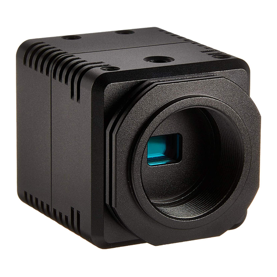
STC-HD203 Series Color CMOS Camera
STC-HD203DV
STC-HD203DV-CS (DVI output / CS mount)
STC-HD203SDI
STC-HD203SDI-CS (SDI output / CS mount)
Product Specifications and Users Guide
STC-HD203DV / STC-HD203DV-CS / STC-HD203SDI / STC-HD203SDI-CS
Product Specifications and Users Guide
(DVI output / C mount)
(SDI output / C mount)
No. 13S054-10
1/78
Advertisement
Table of Contents

Related Manuals for Omron STC-HD203 Series


Summary of Contents for Omron STC-HD203 Series
- Page 1 No. 13S054-10 16:9 Format 1080p STC-HD203 Series Color CMOS Camera STC-HD203DV (DVI output / C mount) STC-HD203DV-CS (DVI output / CS mount) STC-HD203SDI (SDI output / C mount) STC-HD203SDI-CS (SDI output / CS mount) Product Specifications and Users Guide STC-HD203DV / STC-HD203DV-CS / STC-HD203SDI / STC-HD203SDI-CS...
-
Page 2: Table Of Contents
No. 13S054-10 Table of Contents Product Precautions .................... 6 Warranty ........................ 6 Introduction ......................7 Features ............................ 7 Naming Method ........................7 Peripheral Equipment ......................7 Specifications ....................... 8 Electronic specifications ......................8 STC-HD203DV / STC-HD203DV-CS ....................8 STC-HD203SDI / STC-HD203SDI-CS ....................9 Spectral Sensitivity Characteristics .................. - Page 3 No. 13S054-10 Button Description ......................... 18 The Difference of uCOM register and DSP register ............. 18 Functional Description......................19 The communication protocol specifications ............ 34 Communication settings......................34 Communication format ......................34 Camera control commands ....................35 The command list for the communication ..................35 Slave address for the ICs (8 bits) list .....................
- Page 4 No. 13S054-10 Precautions for safe use Please read carefully this “Precautions for safe use” before use the camera. Then the camera uses correctly with agreeing with below notes. In this “Precautions for safe use”, notes divides into “Warning” and “Caution” to use the camera safety and prevent to harm and damage.
- Page 5 No. 13S054-10 Caution The camera housing is not connecting to 0 V It is necessary to wiring and mounting that is line of camera inside circuit. specified in the specifications for this camera. There is a risk of short circuit between camera This will cause of fire or malfunction.
-
Page 6: Product Precautions
No. 13S054-10 Product Precautions Do not give shock to the camera. Do not haul or damage the camera cable. Do not wrap the camera with any material while using the camera. This will cause the internal camera temperature to increase. -
Page 7: Introduction
No. 13S054-10 3 Introduction This document describes the specification of the following cameras: STC-HD203DV / STC-HD203DV-CS (DVI output model) STC-HD203SDI / STC-HD203SDI-CS (SDI output model) 3.1 Features 1080p CMOS Sensor DVI / SDI Output Camera adjustment with OSCD (On Screen Character Display) through Remoter Controller (Option) Configurable many parameters through Control Software ... -
Page 8: Specifications
No. 13S054-10 4 Specifications 4.1 Electronic specifications STC-HD203DV / STC-HD203DV-CS Model Number STC-HD203DV STC-HD203DV-CS Image Sensor 1/2.8" 2.3M Progressive Color CMOS (SONY: IMX136) Shutter Type Rolling Shutter HD Active Picture Elements 1,920 (H) x 1,080 (V) Cell Size 2.8 (H) x 2.8 (V) µm Sync. -
Page 9: Stc-Hd203Sdi / Stc-Hd203Sdi-Cs
No. 13S054-10 STC-HD203SDI / STC-HD203SDI-CS Model Number STC-HD203SDI STC-HD203SDI-CS Image Sensor 1/2.8" 2.3M Progressive Color CMOS (SONY: IMX136) Shutter Type Rolling Shutter HD Active Picture Elements 1,920 (H) x 1,080 (V) Cell Size 2.8 (H) x 2.8 (V) µm Sync. System Internal Minimum Scene Illumination 0.6 Lux (AGC ON) @F1.2... -
Page 10: Spectral Sensitivity Characteristics
No. 13S054-10 4.2 Spectral Sensitivity Characteristics Wavelength (nm) STC-HD203DV / STC-HD203DV-CS / STC-HD203SDI / STC-HD203SDI-CS 10/78 Product Specifications and Users Guide... -
Page 11: Mechanical Specifications
No. 13S054-10 4.3 Mechanical Specifications STC-HD203DV / STC-HD203DV-CS Model Number STC-HD203DV STC-HD203DV-CS Dimensions 40 (W) x 40 (H) x 48.9 (D) mm (*1) 40 (W) x 40 (H) x 43.9 (D) mm (*1) Optical Filter IR cut filter with OPLF Material Aluminum (AC) Lens Mount (*2) -
Page 12: External Control Specification
No. 13S054-10 4.5 External Control Specification Circuit Diagram of SW Board to connect 3.5φStereo Pin Jack 1.8K 3.3K 4.7K SW-A SW-B SW-C SW-D SW-E SW-F STC-HD203DV / STC-HD203DV-CS / STC-HD203SDI / STC-HD203SDI-CS 12/78 Product Specifications and Users Guide... -
Page 13: 3. Dimensions
No. 13S054-10 5 3. Dimensions 5.1 STC-HD203DV unit: mm STC-HD203DV / STC-HD203DV-CS / STC-HD203SDI / STC-HD203SDI-CS 13/78 Product Specifications and Users Guide... -
Page 14: Stc-Hd203Dv-Cs
No. 13S054-10 5.2 STC-HD203DV-CS unit: mm STC-HD203DV / STC-HD203DV-CS / STC-HD203SDI / STC-HD203SDI-CS 14/78 Product Specifications and Users Guide... -
Page 15: Stc-Hd203Sdi
No. 13S054-10 5.3 STC-HD203SDI unit: mm STC-HD203DV / STC-HD203DV-CS / STC-HD203SDI / STC-HD203SDI-CS 15/78 Product Specifications and Users Guide... -
Page 16: Stc-Hd203Sdi-Cs
No. 13S054-10 5.4 STC-HD203SDI-CS unit: mm STC-HD203DV / STC-HD203DV-CS / STC-HD203SDI / STC-HD203SDI-CS 16/78 Product Specifications and Users Guide... -
Page 17: Control Software User's Guide
No. 13S054-10 6 Control Software User’s Guide System Requirements +12V DC Power Supply: UN310-1210 Communication Tool (Communicate through USB port on PC): JIG-USB-HD Control Software: JTACtrl Basic Operating Procedure Connect the power supply with the camera, and connect the Communication Tool with PC via USB cable After installing JTACtrl, control software can be launched from JTACtrl.exe. -
Page 18: Button Description
No. 13S054-10 Button Description Read All Read out All of DPS register and uCOM register values on camera. Please execute this button when turning on the camera every time. DSP -> EEPROM Save the DSP register values (that values are on DSP tab) into the EEPROM. uCOM ->... -
Page 19: Functional Description
No. 13S054-10 6.5 Functional Description DSP: Shutter/GainTab AE mode Normal Long USER Mode can be selectable. If User likes to use Fixed Gain, Fixed Shutter, USER mode should be selected. Convergence luminance This setting is target luminance at which AE has converged to the appropriate luminance. AE convergence speed This setting is used to set the time to be taken for the exposure amount appropriate for the image to be established. - Page 20 No. 13S054-10 Normal AE When Normal AE is selected, these registers are available. As for the detail, please refer to the another chapter. Long AE When Long AE is selected, these registers are available. As for the detail, please refer to another chapter.
- Page 21 No. 13S054-10 USER Mode When User likes to use Fixed Gain or Fixed Shutter, this mode can be used when USER mode is selected on mode. When USER Mode is selected, these registers are available. As for the detail, please refer to another chapter.
- Page 22 No. 13S054-10 Pull-in Step for Full Open When set the number of steps for full open mode pull-in, the convergence speed is faster. USER Mode When White Balance mode is on USER mode. Fixed White Balance can be set. When USER Mode is selected, these registers are available.
- Page 23 No. 13S054-10 DSP: Gamma Gamma Mode Manual or Preset value (0.45,0.6,0.8,1.0) can be selected. When Manual is selected, Gamma curb that was defined on Manual Gamma part are reflected. Gamma Output Selection Gamma Converted Output or Gamma un-Converted Output can be selected. When Gamma Converted Output is selected, Output video image output from Gamma Mode’s value.
- Page 24 No. 13S054-10 DSP: Chroma Hue Adjustment The hue can be adjusted. Saturation Adjustment The Saturation can be adjusted. DSP: AE Other Flickerless mode Flicker is generated when shooting under fluorescent lights whose flickering periods differ from the shutter periods. This is function capable of reducing the flicker by adjusting the shutter speed(Auto,50Hz,60Hz) so as to match the light-emitting frequency of the fluorescent lights.
- Page 25 No. 13S054-10 DSP: Other Resolution/FrameRate Select the output video format. Image Output Inversion Select the H,V Inversion image. Sharpness Gain Set the Sharpness value. ATR-EX function when both low-luminance areas and high-luminance areas exist on one screen, AE controls the exposure in such a way that the exposure is appropriate for the high-luminance areas, loss of dark detail will occur;...
- Page 26 No. 13S054-10 DSP: Aperture The aperture compensation function is used to enhance the perceived resolution by emphasizing the edge areas of the images. To emphasize the edges, increase the aperture compensation gain value. However, if this gain is increased too much, noise which manifests as a roughness of the images becomes noticeable. Adjust the parameter changes while monitoring the actual images.
- Page 27 No. 13S054-10 DSP: Marker Set the Horizontal/Vertical line marker and shadow. Marker Set the line marker and shadow. Line Marker Set the color, position, size of two line markers. Shadow Mask Set the shadow mask on top, bottom, left, right side. STC-HD203DV / STC-HD203DV-CS / STC-HD203SDI / STC-HD203SDI-CS 27/78 Product Specifications and Users Guide...
- Page 28 No. 13S054-10 Circle Marker Set the color, position, size (circle and line) of the circle maker. STC-HD203DV / STC-HD203DV-CS / STC-HD203SDI / STC-HD203SDI-CS 28/78 Product Specifications and Users Guide...
- Page 29 No. 13S054-10 DSP: Pseudo Picture mode selection Select the Normal color or Pseudo color mode. When Pseudo is selected, bipolarization video image is output. Background pseudo color Convert the background image into selected color. Over graphics pseudo color Convert the Over graphics image into selected color. Normal color mode shadow mask line color Select the line color of shadow mask from black or Over graphics pseudo color.
- Page 30 No. 13S054-10 uCOM: User Color Define the eight color table. The defined color can be used as Pseudo color and Line marker.. STC-HD203DV / STC-HD203DV-CS / STC-HD203SDI / STC-HD203SDI-CS 30/78 Product Specifications and Users Guide...
- Page 31 No. 13S054-10 uCOM: Other User Preset Set the DSP setting from eight Preset0 to Preset7. All of DSP setting parameter may reflect after readout. Digital Zoom Set the Digital Zoom. Digital zoom pan Set the offset on horizontal direction. Digital zoom tilt Set the offset on vertical direction.
- Page 32 No. 13S054-10 uCOM: Push Button Button Single push/Hold can be assigned on remote controller’s push button. Marker shadow Remote controller can set the Marker and Shadow parameters. Push button (single push/hold) Select the function for each putton.As for the selectable functions, please refer to another chapter.
- Page 33 No. 13S054-10 uCOM: UART Set the camera communication. uCOM: ReadOnly Read the Firmware and FPGA revision on the camera. OSD Command Test OSCD (On Screen Character Display) 画面の指定した位置に文字を表示することが可能です。詳細は コマンドを 参照ください。 Blemish Pixel Correct the white pixels to interpolated pixel data automatically. Field: Table All of register setting from the registers.
-
Page 34: The Communication Protocol Specifications
No. 13S054-10 7 The communication protocol specifications 7.1 Communication settings Setting Value Baud rate 9,600 bps / 19,200 bps / 38,400 bps (Default) Data bit 8 bits Parity None Stop bit 1 bit Flow control None 7.2 Communication format The format for the sending / receiving data between the PC and the camera is in below: Command Direction Data length... -
Page 35: Camera Control Commands
No. 13S054-10 7.3 Camera control commands All data in this section is described in Hexadecimal format (HEX). The command list for the communication Command Details (HEX) The format for reading data to the camera IC’s is as follows: In the case of writing, since maximum number of addresses can be written at once is 32 addresses, data must be written 8 times separately if 256 bytes data must be written. - Page 36 No. 13S054-10 Command Details (HEX) The format for writing data to the camera IC’s is as follows: Send Data 02, 4A, [DataLenH] + 80, [DataLenL], [SLV], [START_H], [START_L], [END_H], [END_L], [DATASTART], [DATASTART + 1], … , [DATAEND], [CHK], 03 [CHK] = Lower 8bits of “4A + ([DataLenH] +80) + [DataLenL] + [SLV] + [START_H] + [START_L] + [END_H] + [END_L] + [DATASTART] + [DATASTART + 1] + …...
-
Page 37: Slave Address For The Ics (8 Bits) List
No. 13S054-10 Slave address for the ICs (8 bits) list Slave Address 詳細 DSP data EEPROM The Virtual EEPROM zone for the currently selected DSP preset mode of Preset0 to Preset7 EEPROM The EEPROM zone for the Preset0 DSP data EEPROM The EEPROM zone for the Preset1 DSP data EEPROM... -
Page 38: The Ucom Register Mapping List
No. 13S054-10 7.4 The uCOM register mapping list * Please do not change “Reserved data”. Address Descriptions Default User Preset DSP register setting can save on eight Preset areas. * When this vale saves to the EEPRM, camera starts with saved DSP mode at power up. - Page 39 No. 13S054-10 Address Descriptions Default User defined color 0 Red User defined color 0 Green User defined color 0 Blue User defined color 1 Red User defined color 1 Green User defined color 1 Blue User defined color 2 Red User defined color 2 Green User defined color 2 Blue User defined color 3 Red...
- Page 40 No. 13S054-10 Address Descriptions Default 02C - Reserved Default function of primary switch WB: single push * As for the detail of selectable function, please refer to Push button function list Default function of external switch A: single push * As for the detail of selectable function, please refer to Push button function list Default function of external switch B: single push * As for the detail of selectable function, please refer to Push...
- Page 41 No. 13S054-10 Address Descriptions Default OSD menu color 0: Black 1: Blue 2: Green 3: Cyan 4: Red 5: Magenta 6: Yellow 7: White OSD character size 0: Large 1: Small Reserved OSD horizontal display position 0: Left to 256: Right OSD vertical display position 0: Top to 256: Bottom 053 -...
- Page 42 No. 13S054-10 Address Descriptions Default Shadow Horizontal min position [little-endian] (for Push Button) Shadow Horizontal max position [little-endian] (for Push Button) 1,920 Shadow Vertical min position [little-endian] (for Push Button) Shadow Vertical max position [little-endian] (for Push Button) 1,080 070 - Reserved STC-HD203DV / STC-HD203DV-CS / STC-HD203SDI / STC-HD203SDI-CS 42/78...
-
Page 43: Push Button Function On Meru
No. 13S054-10 Push Button Function on Meru When menu is displayed, the following function is assign for each Push Button. WB: Increase Page increase page number SW A: Return Close the menu SW B: Increment Increment cursor or value cursor or value SW C: Select Left Select left selection SW D: Execute... -
Page 44: Push Button Function List
No. 13S054-10 Push button function list Value Function Function Description 0x00 Disabled Disable Push button control 0x01 Display Menu Display Menu on the screen 0x02 Push Lock WB [Save] Execute Push Lock White Balance. And save the setting as AWB HOLD on the EEPROM 0x03 WB mode(AWB) [Save]... -
Page 45: The Dsp Register Mapping List
No. 13S054-10 7.5 The DSP register mapping list * Please do not change access “Reserved data”. Address Descriptions Default AE mode 0: Normal AE 1: Long AE 2: USER mode Reserved Normal AE maximum shutter time [little-endian] 1 step 0.1 mseconds, 1 (100 useconds) to 400 (40 mseconds) Reserved Normal AE maximum gain [little-endian] 1 step 0.3 (dB), 4 (1.2 dB) to 150 (45.0 dB) - Page 46 No. 13S054-10 Address Descriptions Default AE convergence speed Set the convergence speed Max:10、When larger number set, AE works slower. Convergence end dead band range Frame count for outside the dead band AE tracking start dead band range Reserved STC-HD203DV / STC-HD203DV-CS / STC-HD203SDI / STC-HD203SDI-CS 46/78 Product Specifications and Users Guide...
- Page 47 No. 13S054-10 Normal AE When AE Mode =0[h] was selected, the normal AE mode is established. In this AE mode, the gain and exposure time are automatically adjusted so that the images have the appropriate brightness. Maximum Exposure time can be set on Normal AE maximum shutter time (0x001-0x002). Maximum Gain can be set on Normal AE maximum gain (0x004-0x005).
- Page 48 No. 13S054-10 USER mode When AE Mode = 2[h] was selected, the USER mode is established. In this USER mode, the gain and exposure time can be configured. If exposure time is longer than Normal AE maximum shutter time, Long AE mode will be available. Exposure time can be set on USER mode shutter time (0x012 - 0x013).
- Page 49 No. 13S054-10 Frame count for outside the dead band This function is used to ensure that the AE operation will not overly respond to changes in the subject when an object has passed cut across the shooting screen while AE is in the appropriate status. Tracking is started when the AE error amount is above the setting and this has continued for at least the number of Frame count for outside the dead band frames.
- Page 50 No. 13S054-10 Address Descriptions Default White Balance Mode 0: Auto 1: Full Open 2: AWB Hold 3: USER Mode Reserved Push Lock (After the Push Lock, White Balance mode turn to the AWB mode automatically) 0:OFF 1:ON (Automatically turn 0, after convergence) AWB Pull-in Delay Unit: Frame number When a status outside the dead band has been detected in the ATW mode,...
- Page 51 No. 13S054-10 White Balance ・Auto (Auto Trace White balance) AWB Pull-in Speed, AWB Pull-in Delay, Convergence Step can be configurable. This function sets the pull-in frame and target frame and automatically tracks the changes in the color temperature to adjust the white balance.
- Page 52 No. 13S054-10 Address Descriptions Default Gamma Mode 0: Manual 1: 0.45 2: 0.6 3: 0.8 4: 1.0 Gamma Output Selection 0: Converted Output 1: Unconverted Output Reserved Manual Gamma 00 [little-endian] Manual Gamma 01 [little-endian] Manual Gamma 02 [little-endian] Manual Gamma 03 [little-endian] Manual Gamma 04 [little-endian] Manual Gamma 05 [little-endian] Manual Gamma 06 [little-endian]...
- Page 53 No. 13S054-10 Address Descriptions Default Manual Gamma 20 [little-endian] 1,348 Manual Gamma 21 [little-endian] 1,360 Manual Gamma 22 [little-endian] 1,372 Manual Gamma 23 [little-endian] 1,388 Manual Gamma 24 [little-endian] 1,404 Manual Gamma 25 [little-endian] 1,420 Manual Gamma 26 [little-endian] 1,436 Manual Gamma 27 [little-endian] 1,452 Hue Adjustment (Two's complement)
- Page 54 No. 13S054-10 Address Descriptions Default Line Marker 0: Disable 1: Enabler Shadow Mask 0: Disable 1: Enable Circle Mask 0: Disable 1: Enable Reserved Marker 0: Disable 1: Enable Shadow mask shading level 0: Invisible to 255: Black Horizontal shadow mask top position [little-endian] 0: Top to 1,080: Bottom Horizontal shadow mask bottom position [little-endian] 1,080...
- Page 55 No. 13S054-10 Address Descriptions Default Circle marker color *as for the configurable color, please refer to the color code chart Circle marker radius Circle marker thickness Circle marker center position (horizontal) Circle marker center position (vertical) Picture mode selection 0: Normal 1: Pseudo Normal color mode shadow mask line color 0: Black...
- Page 56 No. 13S054-10 Color Code Table 16 defined colors can be selected from following table and these colors can be refer to Line Marker and Pseudo Color. As for User Defined Color 0 to 7, user can configure these colors setting through serial communication. Code Color Black...
-
Page 57: Oscd (On Screen Character Display) Command
No. 13S054-10 OSCD (On Screen Character Display) Command 2 Byte Command Note: The data have to send as follow order D15-D8, D7-D0. Function Video RAM Batch Clear Command Display Control Command Character Size Control Command Write Address Control Command Character Size Control Command Function Video RAM Batch... - Page 58 No. 13S054-10 Character Size Control Command Set the character size for each RAW. SV1, SV0: Size on Vertical (00: x1, 01: x2, 02: x3, 03: x4) SH1, SH0: Size on Horizontal (00: x1, 01: x2, 02: x3, 03: x4) AR3, AR2, AR1, AR0: RAW (0 to 11) STC-HD203DV / STC-HD203DV-CS / STC-HD203SDI / STC-HD203SDI-CS 58/78...
-
Page 59: Byte Consecutive Command
No. 13S054-10 2 Byte consecutive Command Note: The data have to send as follow order D15-D8, D7-D0. Functions Display Character Control Command Functions Display Character Control Command Display Character Control Command Set the Writing character data, character color, blink data into Video RAM address. This command is 2 Byte consecutive command, if more than 2 consecutive character writing are required, just send only lower 8bits (C7 to C0). -
Page 60: Camera Instruction Guide
No. 13S054-10 8 Camera instruction guide This camera can be set through three setting settings as follows. A. Push Button B. External Switch (Remote controller: RC-HD133) *option C. Through the control software *as for the detail, please refer to the another chapter Push Button White Balance can be set through push button. -
Page 61: Camera Setting Through External Switch (Remote Controller)
No. 13S054-10 8.2 Camera Setting through External Switch (Remote Controller) Remote controller (Model:RC-HD133) is option, remote controller is not included camera Camera Setting through Switch that has 3.5φStereo Pin Jack A. Please assign each function through control software in advance B. -
Page 62: Menu On Screen With External Switch
No. 13S054-10 Menu on screen with External Switch Page 1 PAGE 1 2 3 4 5 6 AE MODE NORMAL LUMINANCE 00000 PRI GAIN 27.09 dB PRI SHUTTER 0000 1/1000s USER GAIN 46.2dB USER SHUTTER 0000 1/1000s GAMMA 0.45 1) AE MODE Selects the exposure and the gain operation mode from below three modes. - Page 63 No. 13S054-10 2) LUMINANCE Sets the target Brightness for the “normal” and “long” auto exposure and the auto gain operation. The brightness image maintains with the auto exposure and the auto gain operation. Setting range: 0 (Dark) to 65,535 (Bright) Default: 4,608 3) PRI GAIN Sets the fixed gain for the “normal”...
- Page 64 No. 13S054-10 Page 2 PAGE 1 2 3 4 5 6 WB MODE USER R/G 00000 USER B/G 00000 OFFSET CONTRAST SHARPNESS H04 V06 COR03 1) WB MODE Selects the white balance mode from below four modes. (Default: AWB). a) AWB The auto white balance.
- Page 65 No. 13S054-10 5) SHARPNESS Sets the Sharpness (Edge Enhancement) of the image (Default: 0). a) H Sets the horizontal sharpness. Setting range: 0 (Soft) to 15 (Strong) Default: 0 b) V Sets the vertical sharpness. Setting range: 0 (Soft) to 15 (Strong) Default: 0 b) COR The noise level also emphasizes when using the sharpness function.
- Page 66 No. 13S054-10 Page 3 PAGE 1 2 3 4 5 6 GRAPHICS LINE LINE1 POS 0000 SIZE 0000 COLOR BLACK POS 0000 SIZE 0000 COLOR BLACK LINE2 POS 0000 SIZE 0000 COLOR BLACK POS 0000 SIZE 0000 COLOR BLACK 1) GRAPHICS Selects enable or disable for the line makers and the shadow mask display.
- Page 67 No. 13S054-10 b) H SIZE Sets the size (thickness) for the horizontal line 1. Setting range: 0 (0 line, no horizontal line) to 1,080 (1,080 lines) Default: 0 c) H COLOR Sets the color for the horizontal line 1. It is necessary to set the USER0 to USER7 colors with the PC communication. Setting selection: BLACK / WHITE / RED / GREEN / BLUE / CYAN / MAGENTA / YELLOW / USER0 / USER1 / USER2 / USER3 / USER4 / USER5 / USER6 / USER7 Default: BLACK...
- Page 68 No. 13S054-10 d) V POS Sets the position for the vertical line 2. Setting range: 0 (Left end) to 1,920 (Right end) Default: 0 e) V SIZE Sets the size (thickness) for the vertical line 2. Setting range: 0 (0 pixel, no vertical line) to 1,920 (1,920 pixels) Default: 0 F) V COLOR Sets the color for the vertical line 2.
- Page 69 No. 13S054-10 Page 4 PAGE 1 2 3 4 5 6 GRAPHICS SHADOW GRADE 000 T 0000 B 1020 L 0000 R 1280 CIRCLE RADIUS 000 SIZE 000 POS 0960 POS 0540 COLOR BLACK 1) GRAPHICS Selects enable or disable for the line makers and the shadow mask. (Default: ON). This function in the page3 and in the page4 is the same function.
- Page 70 No. 13S054-10 e) SHADOW V R Sets the position for the right area of the shadow mask. Setting range: 0 (Left) to 1,920 (Right) Default: 0 LINE2 V POS LINE1 V POS Vertical line 1 Vertical line 2 SHADOW H T LINE1 H POS Horizontal line 1 SHADOW H B...
- Page 71 No. 13S054-10 4) CIRCLE Selects enable or disable for the circle maker display (Default: ON). This setting is only valid when “GRAPHICS” is “ON”. a) ON The circle maker can be display. Sets the radius, the line size (thickness), the center position and the color for the circle maker. b) OFF The circle maker does NOT display.
- Page 72 No. 13S054-10 RADIUS COLOR H POS, V POS SIZE STC-HD203DV / STC-HD203DV-CS / STC-HD203SDI / STC-HD203SDI-CS 72/78 Product Specifications and Users Guide...
- Page 73 No. 13S054-10 Page 5 PAGE 1 2 3 4 5 6 RES / FPS 1080P60 OSD SIZE LARGE PROFILES PRESET0 PATTERNS IMAGE OUTPUT STANDARD 1) RES / FPS Sets the image format and the frame rate for the video output from below nine output formats. Please changes the video output format and the frame rate to match the specifications for the monitor or the capture devices.
- Page 74 No. 13S054-10 4) PATTERNS Selects the output signal from below four output signals. a) OFF The video is output from the camera. b) GRAY The gray scale test pattern is output from the camera. c) COLOR The color test pattern is output from the camera. d) GRAY+COLOR The color pattern (Top) + gray scale (Bottom) test pattern is output from the camera.
- Page 75 No. 13S054-10 Page 6 PAGE 1 2 3 4 5 6 EEEPROM SAVE 1) EEPROM The camera settings in the page1 to page5 can be saved into the camera as the PRESET. OSD SIZE and PATTERNS settings cannot be saved. To change the PRESET, select PRESET and use this function after change the settings.
-
Page 76: Revisions
No. 13S054-10 9 Revisions Date Changes Note 2014/03/20 New Document: Release Production model Added Camera instruction guide 2014/04/28 Revised Added Pixel Blemish correction 2014/06/27 Revised Added Weight of SDI model Changed company name 2014/07/14 Revised Updated Minimum scene illumination 2014/10/10 Revised Marked Lens information 2014/12/02... - Page 77 No. 13S054-10 STC-HD203DV / STC-HD203DV-CS / STC-HD203SDI / STC-HD203SDI-CS 77/78 Product Specifications and Users Guide...
- Page 78 No. 13S054-10 19F, Ebina Prime Tower 9-50, Chuo 2 chome Ebina-city, Kanagawa 243-0432 Japan TEL 81-46-236-6660 FAX 81-46-236-6661 URL http://www.sentech.co.jp/ STC-HD203DV / STC-HD203DV-CS / STC-HD203SDI / STC-HD203SDI-CS 78/78 Product Specifications and Users Guide...
Need help?
Do you have a question about the STC-HD203 Series and is the answer not in the manual?
Questions and answers