
Related Manuals for Kingfisher KI2000 Series


Summary of Contents for Kingfisher KI2000 Series
- Page 1 KI 23400 Series Two Way Test Set + ORL KI 27400 Series Two Way Loss Test Set OPERATION & MAINTENANCE GUIDE...
- Page 2 IEC 60825-2:2004 Safety of laser products - Safety of optical fibre communication systems (OFCS) CFR 21part 1040.10 (USA) Performance standards for light- emitting products-Laser products Supplemental Information: The product was tested in a typical configuration with Kingfisher International test systems. 17 March 2020 Bruce Robertson...
- Page 3 To get the best use from your instrument and to ensure its safe operation, please spend a few minutes to read this manual. Made in Australia. International © Copyright Kingfisher International Pty Ltd Edition 2, Sep 2020 KI23400/KI27400 UM-2...
-
Page 4: Table Of Contents
Battery & External Power ..........16 Autotest General Operation ..........30 Disabling Battery Charging ..........16 Autotest Operation ............31 Enabling Battery Charging ..........16 Kingfisher Autotest Compatibility........31 Push-On Optical Connector .......... 19 Autotest Two-Way Operation ........32 Power Meter ..............19 KI23400/KI27400 UM-2... - Page 5 CONTENTS Two-Way Referencing ............32 Instrument Memory Operation ........50 Length Measurement ............33 Recording Data to Memory ..........50 Autotest One-Way Operation ........34 Recalling Stored Data from Memory ......... 50 One-Way Referencing ............34 Re-Test or Over-Write Results .......... 51 Autotest User-To-User Communication ......
- Page 6 CONTENTS Ordering Information ............. 70 Calibration & Maintenance ..........73 Performance Verification Tests ........75 Power Meter ..............76 Light Source ..............76 Two Way Autotest ............. 78 One Way Autotest ............. 80 Length measurement ............81 Optical Return Loss............81 Required Equipment ............
-
Page 7: Pictures Of Instrument
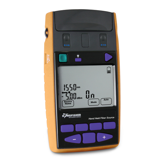
Pictures of Instrument Flip-over connector Connector release cover & tilt bail & port identifier Display Lugs for Backlight Carry Strap Memory USB store Labelling: On/Off Compliance Model No Basic Operation Battery compartment Toggle Centre Anti-slip strip KI23400 / 27400 HANDHELD 2-WAY LOSS TEST METER KI23400/KI27400 UM-2... - Page 8 Micro USB port for data and power Full-segment picture of LCD Slim, easy USB port for to hold memory stick KI23400 / 27400 HANDHELD 2-WAY LOSS TEST METER KI23400/KI27400 UM-2...
-
Page 9: Applications Support
Please visit www.kingfisherfiber.com to see our comprehensive manual. To obtain service, please contact your local Kingfisher Application Notes written to support instrument users, an updated International distributor or our office in Australia: version of this manual or instrument firmware updates. FAQs can be found in the “Support”... -
Page 10: Introduction And Applications
INTRODUCTION AND APPLICATIONS The tough housing has shock-absorbing rubber corners for drop protection. The latest materials and methods are used to produce an Introduction and Applications elegant, yet rugged instrument. Battery life is 80 – 1000 hours from 2 x AA alkaline or NiMH cells. The KI2000 family of Two-Way Optical Loss Test Sets are used to test Instruments can be externally powered or charged via micro USB. -
Page 11: Memory And External Software Features
INTRODUCTION AND APPLICATIONS With just one button push and high accuracy, a single fiber connected micro SD card using a suitable adaptor), via the Type A USB port, between two instruments can test & pass / fail at several wavelengths for later analysis on KITS™... -
Page 12: Orl Meter Features
INTRODUCTION AND APPLICATIONS Test time for Bidirectional Autotest Two-Way Loss, ORL and Length Various detector options include Indium Gallium Arsenide (InGaAs), is typically a few seconds per fiber, with major savings in skill, time, Germanium (Ge), Silicon (Si) and high-power versions. cleaning materials and test confidence. -
Page 13: Light Source Features
INTRODUCTION AND APPLICATIONS A separate reference for each λ is stored and displayed. The optional and innovative VFL VisiTester option is helpful for general loss testing, continuity testing and fault finding. In VisiTester When performing loss testing using an Autotest light source, up to mode, it intermittently illuminates the connected test fiber with a red three λ... -
Page 14: Test Standards Compliance
✓ Reporting software can be easily updated with new or in- house test standards ✓ Kingfisher can also supply suitable quality microscopes and This equipment has features that help users comply with many international cabling test standards. Proper compliance is also a... -
Page 15: General Safety Summary
Kingfisher International assumes no liability for the contents of the shipment for completeness and verified the instrument customer’s failure to comply with these requirements. -
Page 16: Operating Environment
Operating Environment could create a hazardous optical condition. For service, these devices The range of Kingfisher equipment covered by this manual can be must be returned to an authorised service centre, and unauthorised operated at temperatures between -15 °C and +55 °C and at relative modification or adjustment must not be performed. - Page 17 GENERAL SAFETY SUMMARY Kingfisher Two-Way Tester Laser Eye Safety Information IEC 60825-2 (2011) – Class 1 650 nm, MM or SM fiber 1.95 mW This information on laser eye safety compliance covers all standard 850 nm, MM or SM fiber 3.88 mW...
-
Page 18: Battery & External Power
BATTERY AND EXTERNAL POWER When the instrument is being externally powered, and is not charging the battery, no battery symbol shows. Battery & External Power When the instrument is being externally powered, and is also charging the battery, an animated battery symbol shows like The instrument can be powered by battery or external input, and if this. - Page 19 BATTERY AND EXTERNAL POWER suggest that in this case, the battery compartment should be sealed (e.g. with an anti-tamper label), since attempting to recharge non- rechargeable batteries may lead to acid leakage and instrument damage. Battery charge current is up to 0.2 A, giving a charge time of 6.5 hours for a 1.3 A-hr battery with the instrument off.
- Page 20 BATTERY AND EXTERNAL POWER CAUTION! Do not use rechargeable lithium-ion batteries or any battery with a voltage over 1.8 V. This will damage the instrument. CAUTION! Do not mix battery types. CAUTION! Change all batteries as a group. Please help protect our environment, by re-cycling your old batteries. KI23400/KI27400 UM-2 18 -...
-
Page 21: Push-On Optical Connector
PUSH ON OPTICAL CONNECTOR When not in use, keep test ports and connectors covered. Never touch connector tips with your fingers since body oils and dirt can impair Push-On Optical Connector performance. Refer to ordering information section in this manual to see our wide This section applies to instruments with push-on pull-off interchangeable range of available adaptor styles. -
Page 22: Light Source
PUSH ON OPTICAL CONNECTOR The power meter is in the middle How To Clean Optical Connectors Symbol colour Always clean the mating connector tip and ferrule before mating, using shows port type approved materials. Port Details CAUTION! Never attempt to clean connector interfaces with abrasive Label cleaners, or sharp or hard objects. -
Page 23: When To Clean The Optical Connectors
PUSH ON OPTICAL CONNECTOR If this is not enough, then clean the interface by rubbing a lint-free lens cloth over the surface using small circular movements. Connector Wear: Fiber Optic Connectors usually have a design life of around 1,000 insertions before they are worn out. So, if your instrument has had considerable use, the removable connector adaptor may be worn out, and need replacing. -
Page 24: Screw-On Optical Connector
SCREW ON OPTICAL CONNECTOR To fit a new adaptor, just screw it onto the detector head. Do not use excessive force. Screw-On Optical Connector Ge7 detectors only: When fitting an MPO connector adaptor, continue turning the adaptor clockwise until a “click” is felt. At this point, the This section applies to power meter ports with large area detectors adaptor is rotationally aligned with the rectangular optical detector. - Page 25 SCREW ON OPTICAL CONNECTOR • Using compressed air, blow out the pinhole in the connector adaptor, and carefully inspect for cleanliness. Dirt can get stuck in the pinhole. When performing precision measurements, it is usually helpful to have an APC connector plugged into a power meter, to reduce line reflections.
-
Page 26: Getting Started & Turning On
GETTING STARTED AND TURNING ON If the instrument does not respond, change the batteries or apply external power to the micro USB connector, or refer to the end of this Getting Started & Turning On section to perform a hard re-start. The battery condition is indicated with the battery symbol This section is helpful when getting started and, gives basic instrument on the display. -
Page 27: Backlight
GETTING STARTED AND TURNING ON To return to the main menu, press button below [HOME] or F1 At start up, the following information is displayed The following instructions show basic power meter and light source • “Perm” if the instrument will stay on operation only, to help you get started. -
Page 28: Basic Light Source
GETTING STARTED AND TURNING ON The display shows: nm, dBm, dB, reference power Once you have established that the equipment is working, and used some simple functions you may want to: • Press button below [METER MODE] to toggle log (dB) / linear •... -
Page 29: Setting Time & Date
SETTING DATE AND TIME • To exit without saving new settings, press button below Setting Time & Date [Cancel] (F1). Test date and time are stored with test results. So, if the instrument memory is used to record results, the user probably wants to set the correct date and time. -
Page 30: Menu Navigation Tips
MENU NAVIGATION TIPS recognised (shown on the LCD), this button dumps the Menu Navigation Tips entire memory into a new file on the USB key. For your later reference, please note the convenient Quick Reference LCD General Information Guide at the back of this manual. Refer also to the display picture at •... -
Page 31: Autotest Overview
Autotest Overview real-time acquisition with KITS™ software. The instrument displays pass / fail / marginal. Autotest is a mature Kingfisher fiber optic test data transfer protocol in use since 1994. It has been extended various times within its original One-Way Autotest framework. -
Page 32: Autotest Data Saved
λ are successfully transmitted. One-way Autotest is always initiated from the light source end. The excellent test stability of Kingfisher test equipment is highly Autotest provides a real time measurement display. This is very relevant to Autotest operation since the requirement to re-reference convenient to check that a connection looks good and stable before the source &... -
Page 33: Autotest Operation
[Two-Way Autotest only]: To view reference and measured absolute values, press button below [MODE] (F3), then both Any Kingfisher Autotest source (except POF source of 470, 520 nm) / lines of the display show information from the same λ, each power meter / loss test set / two-way tester can be used as a source &... -
Page 34: Autotest Two-Way Operation
AUTOTEST TWO-WAY OPERATION Light sources with up to 3 active λ (excluding VisiTester) per source Autotest Two-Way Operation port will by default cycle through all available λ, unless a reduced/restricted λ-set has been selected, which can help speed up & simplify higher volume testing. This is the typical method of operation with a matched pair of Two- Way instruments, and for Tier 1 testing. -
Page 35: Length Measurement
AUTOTEST TWO-WAY OPERATION To set the reference, enter relative mode, then hold down [Set Ref] for This function is reliable and unaffected by optical line reflections, PC / 3 seconds until the instrument beeps finish. The main display will go APC connector type etc. -
Page 36: Autotest One-Way Operation
AUTOTEST ONE-WAY OPERATION reduced/restricted λ-set has been selected, which can help speed up Autotest One-Way Operation & simplify higher volume testing. To exit Autotest, on the light source end, press [MENU] or disconnect With the Two-Way tester instruments, you are recommended to use a patch lead for more than 8 seconds. -
Page 37: Autotest User-To-User Communication
AUTOTEST USER TO USER COMMUNICATION If the VisiTester option is available, this is a useful feature to help get testing started: If one instrument at one end is hooked up and Autotest Autotest User-To-User activated, the active fiber at the far end will flash, so the user at this Communication end knows that the test is ready to start, and which fiber to start on. -
Page 38: Autotest Λ Restriction
AUTOTEST λ RESTRICTION • To test with the lower bank / MM group only: Press + and [Auto] Autotest λ Restriction (F4) together. • To test with the upper bank / SM group only: Press - and [Auto] (F4) together. Once you are familiar with these instruments, particularly if the instrument has more than two λ, you might want to restrict the number Method 2 (more control) -
Page 39: A Test Lead Verification Test Procedure
TEST-LEAD VERIFICATION TEST source port type which matches the fiber to be tested, eg single mode A Test Lead Verification Test or multimode. Procedure Reference patch-lead Test lead loss repeatability is often a limiting factor in loss test accuracy and repeatability. As a result, test standards may mandate that test lead performance is verified before, during and after testing. - Page 40 TEST-LEAD VERIFICATION TEST • For reference grade connectors, A test-quality lead should typically have a loss of <0.3 dB per end for MM fiber, and 0.5 dB for SM fiber, also including MPO types etc. If a variety of test leads pass this test, you can proceed to testing a system.
-
Page 41: Pass / Fail Testing
PASS / FAL OPERATION sets of one-way results can be merged to create a bidirectional Pass / Fail Testing test. If any limit value is set to 0, it is disabled. Pass/Fail testing and display is useful to ensure that cable tests pass In compliance with TIA standards, the default two-way loss pass/fail is before results are stored in memory. -
Page 42: Pass/Fail Operation
PASS / FAL OPERATION • (or Length test status in the case of 2-way Autotest) is Press button below [SAVE] or [CANCEL] fail. For example, if you select a loss pass value of 2 dB, and a loss • Pass/fail method selection: Marginal value of 3 dB, then any loss less than 2.0 with be a pass For 2-way Autotest: (indicate by ‘✓’... -
Page 43: Continuity & Polarity Test Overview
12 fibers in one pass. quickly identify one fiber out of an array if the labelling is wrong or Note that any Kingfisher Autotest source with Multifiber ID can be absent. used, such as inexpensive KI9800 series instruments. -
Page 44: Power Meter Manual Operation
MANUAL OPERATION-POWER METER • To display, hide or reset minimum and maximum recorded Power Meter Manual Operation power for selected λ, press – and + simultaneously. This is a handy simple data logging function for field use. • Press button below [HOME] to return to Main menu To operate the Optical Power Meter, press [Meter]. -
Page 45: Light Source Manual Operation
MANUAL OPERATION-LIGHT SOURCE • To end modulation, press and hold button below [MODE] then press Toggle Centre. Alternatively, press and hold button Light Source Manual Operation below [MODE] for 3 sec. On the KI274x Series instruments, the light source requires a warmup If the VisiTester VFL option is fitted, the VFL appears as a 650 nm period at the set λ... -
Page 46: Orl Meter Manual Operation
MANUAL OPERATION-OPTICAL RETURN LOSS METER ORL Meter Manual Operation ORL Meter Operation No warmup is needed. Ensure all optical connectors are clean. • ORL is an instrument p/n option. Connect the device under test to the Two-Way port. • Press button below [RETURN LOSS] to display ORL KI23400 Series instruments measure Optical Return Loss (ORL) using measurement, ORL for all available λ... -
Page 47: User Calibration Mode (Ucal)
MANUAL OPERATION-OPTICAL RETURN LOSS METER Perform the zero function whenever the stray ORL condition may have • To re-set both of these features to factory defaults, select changed. [RETURN LOSS], -/+, [Default] then [Set] to store. • To display the stored stray value, select -/+ and then button below [MAX/MIN]. -
Page 48: Vfl-Visitester Operation
VFL-VISITESTER OPERATION Operation: VFL-VisiTester Operation If used with Autotest, no specific action is needed other than to start Autotest. In Autotest mode, the red laser is not included in the VFL-VisiTester is an option, depending on the instrument p/n. displayed test result. If used in stand-alone VFL mode: To switch on the visible laser, press The VFL laser shares the Two-Way port, so it can be used in a few ways, for example:... -
Page 49: Tone Detection & Slow Mode
TONE DETECTION AND SLOW MODE Tone Detection & Slow Mode Slow Mode Tone detection Slow Mode is occasionally useful to measure power on unstable This is a useful feature of both source and meter for quick continuity / signals that accidentally trigger tone detection, or to improve test polarity checking. -
Page 50: Test Recording & Reporting Overview
TEST REPORTING OVERVIEW • More detailed operation and instructions are elsewhere in this manual, or the KITS™ software manual. Test Recording & Reporting Overview • KITS™ software can perform an unformatted data download These instruments can be used various ways to record results and get for any other analysis by the user. -
Page 51: Instrument Memory Overview
INSTRUMENT MEMORY OVERVIEW Up to 20 pre-set text identifiers can be stored for later use, to help manage & identify stored test data per project etc. See Text ID Tag Instrument Memory Overview section for more details. Meter Display Hold Two-Way testers have various features for storing and recording test To hold the display at its current value, press [Hold], then store the data or user settings in non-volatile memory... -
Page 52: Instrument Memory Operation
INSTRUMENT MEMORY OPERATION displayed (see Figure 4 at the end of this section for an LCD Instrument Memory Operation display sample). To change to display more detail with absolute power, loss, reference power for each direction, (see Figure 5 at the end of this section for an LCD display Recording Data to Memory sample) press F3. -
Page 53: Re-Test Or Over-Write Results
INSTRUMENT MEMORY OPERATION • • [For data saved in Meter mode only]: As default, absolute When you have finished re-testing, go to the next empty power will be displayed in dBm along with loss (dB) and location after your results: Enter Memory mode, select the reference power (dBm), see Figure 7 at the end of this desired (e.g. -
Page 54: Instrument Usb Ports
(dBm) KITS software or can be downloaded separately. Kingfisher does not provide API or other support for users to write their own programs to interface to this instrument. Note that the larger USB port marked “MEM” is only used to dump Figure 6. -
Page 55: Text Id Tag Operation
TEXT ID TAG Modify a Text ID Tag • Enter Meter or AUTO menu. Text ID Tag Operation • Press button above “FIBER ID”, then - or + to select a stored ID Tag. Text ID tag is a useful auto-naming feature to systematically pre- •... -
Page 56: Application Of Text Id Tag
Application of TEXT ID Tag ABCDEF1234, ABC1234, ABCDE-012, AB-1234, A-12345, A-1 345, Kingfisher KI2000 Series instruments allow a test technician to quickly label and store test results in the instrument memory. A-BC0123, -40.1234, A02-1234, A02 1234, 1-23012, A-2 012, A.012,... -
Page 57: Usb Key Memory Dump
USB KEY Memory Dump USB Key Memory Dump Instrument Data Sanitization The large USB (Type A) port on the right side of the instrument with To entirely erase all traces of user activity on this instrument: “MEM” (Memory) is used only for dumping a data file onto a USB To erase all parts of the non-volatile user memory, including user data, memory key, it has no other function. -
Page 58: External Kits™ Software
EXTERNAL SOFTWARE • Pass/Fail according to many common test standards can be External KITS™ Software selected, or you can enter details of new or in-house test standards. Pass/Fail parameters created in KITS can be uploaded to a Two-Way tester, to ensure that it has the same Free KITS™... -
Page 59: Tier 1 Test Example
TIER 1 TEST EXAMPLE ✓ Check that instrument has correct connector types ✓ Check inspection & cleaning materials & qty available Tier 1 Test Example ✓ Check you have materials needed to secure or identify post- test access to site, closets, racks, ducts, connections etc. We give here an example of a typical Tier 1 Test / Acceptance / ✓... - Page 60 TIER 1 TEST EXAMPLE ✓ In KITS™, observe the “Secure Mode” symbol which is must Once you have verified that the site & cabling continuity is looking promising, polarity is good, and labelling is good, (all key parts of Tier be active for Tier 1 testing data security 1 testing) it’s time to perform and record the formal loss (maybe ORL) ✓...
- Page 61 TIER 1 TEST EXAMPLE • Go to Test Setup, enter / adjust any relevant data, and set “Number of Tests” to set the spreadsheet size • Go to Terminal ID to name each location • KITS ribbon / ensure “Unset Secure” is locked Start Testing •...
-
Page 62: Care Of Your Instrument
CARE OF YOUR INSTRUMENT CAUTION! Clean the instrument case using soft damp cloth. Do not use strong solvents to avoid risk of damage to surfaces. Care of Your Instrument CAUTION! Input optical power must not exceed the damage level specified for each detector type. CAUTION! Follow the directions in this manual on optical connector care, to avoid permanently damaging the connectors. -
Page 63: Accuracy Considerations
Optimum measurement High power (attenuated) meters tend to suffer overall reduced repeatability is obtained by using of a mandrel wrap close to a source. accuracy. Kingfisher high power meters use a multi-technology Please visit www.kingfisherfiber.com to see our comprehensive attenuating element to reduce the adverse effects of reflections and λ... -
Page 64: Light Source
ACCURACY CONSIDERATIONS Ge detectors should not be used for accurate testing on WDM systems Light Source Light source power may drift. When you have finished a test, go back beyond 1550 nm, since inaccuracies become large and unpredictable. to the start position to check if the light source power is still within CWDM Loss &... - Page 65 ACCURACY CONSIDERATIONS Uncertainty due to +/- 30 nm λ Normalized Power Meter Response tolerance 25ºC 0ºC InGaAs 0.10 0.40 0.40 1300 0.06 0.06 0.01 1550 0.50 0.05 1610 2.80 0.03 Ge 0 ºC Ge 25 ºC InGaAs 1000 1100 1200 1300 1400 1500...
-
Page 66: Definition Of Terms
DEFINITION OF TERMS Short / Long Term (Power) Stability: In CW mode, the uncertainty Definition Of Terms of the power level observed over a given time, compared to the mean Power Meter power during this time. Measured with an averaging optical power meter, a 9/125µm fiber, at constant temperature, within a specified temperature window, and at line voltage. -
Page 67: Specifications
SPECIFICATIONS Case: Rubber/Polycarbonate, 1 metre drop tested. Specifications Display: High contrast custom LCD, 74 x 55 mm / 2.9 x 2.2” Size: 190 x 105 x 35 mm (7.5 x 4.1 x 1.4”) Tone detection: 150 ~ 9999 Hz ±1%. Weight: 420 gm (0.9 lb). - Page 68 SPECIFICATIONS Two-way Autotest specifications: Fiber Type Wavelengths Length Range / Accuracy Loss Range Loss Repeatability / Linearity 5.5 dB (62.5 µm) / 3 m or 1 % 27 dB (62.5 µm) 850, 1300 nm 0.06 dB 3.5 dB, (50 µm) / 3 m or 1 % 24.5 dB (50 µm) 1310, 1550 nm 30 dB / 3 m or 1 %...
- Page 69 SPECIFICATIONS Optical Power Meter: Response Damage Power Midrange Calibration Polarization Total Tone & Sensitivity Calibration level range Autotest linearity Accuracy Sensitivity Uncertainty ± 30 nm Min dBm InGaAs detector 780, 820, 850, 980 +10 ~ -60 < 0.05 0.03 600 ~ 0.04...
- Page 70 SPECIFICATIONS Optical Light Source: 1490 / 1625 nm 850 / 1300 nm 1310 / 1550 nm Comments F-P Laser CWDM7 Laser Refer to ORDERING INFORMATION for 1 dB Power accuracy nominal power level Short term stability (dB) 0.06 / 0.04 0.01 0.04 / 0.03 KI274008 / KI234009...
- Page 71 SPECIFICATIONS VisiTester: Parameters Values Wavelength (nm) 650 ± 5 Power dBm -1 ± 1 SM / MM fiber Laser Safety Class 1, IEC60825-2 Blink rate (manual) CW or 2 Hz ORL: Parameters Laser 1 or 2 3 or 4 0 ~ 40 dB (62.5 µm) Range 0 ~ 65 dB...
-
Page 72: Ordering Information
ORDERING INFORMATION Ordering Information Description Source Power (dBm) @ Fiber Type (µm) Ports Laser VisiTester 62.5 Refer to LIGHT SOURCE SPECIFICATIONS for Power Accuracy specifications KI27400 series: Loss Testing only (some models have VisiTester) Instrument, LTS-2W 850-1300 nm, Ge -25.5 KI27403-Ge Instrument, LTS-2W 1310-1550 nm, InGaAs KI27422-InGaAs... - Page 73 Instrument, LTS-2W ORL Length VisiTester, 1310-1550-1625 nm U/S APC, KI23410OLV-InGaAs-APC InGaAs Standard Accessories: Optional Interchangeable Connector Adaptors: SC metal-free optical connector adaptors, KITS™ PC software (downloadable free from Kingfisher’s website) and USB cable, user Description Description manual, ILAC/ NATA traceable calibration certificates, carry pouch, carry E2000/LSH, blue OPT060...
- Page 74 ORDERING INFORMATION Optional Accessories: Description Option, Carry Case for 2 Instruments OPT153 Option, Carry Case includes Cletop-style cleaner & Cleaning Sticks OPT154B Refer to product brochures on our website, www.kingfisherfiber.com Standard Accessories of specific instrument model, and the available optional accessories & optional interchangeable connector adaptors. 72 - KI23400/KI27400 UM-2...
-
Page 75: Calibration & Maintenance
Note that if using laser or LED sources, the calibration • Using tweezers, place a link across gold plated calibration accuracy will be inferior to the method used by Kingfisher. contacts inside battery compartment, Figure 2. Turn on Please use an APC connector into the power meter, to avoid external power via micro USB. - Page 76 CALIBRATION AND MAINTENANCE • Remove batteries, connect to external USB power. • Using tweezers, place a link across gold plated calibration Gold plated contacts inside battery compartment, Figure 2. Turn on calibration external power via micro USB. contacts • Press [F1] to select source calibration. Press [ + ] or [ - ] to set the λ...
-
Page 77: Performance Verification Tests
PERFORMANCE VERIFICATION TESTS Instrument Specification Specifications are the performance Performance Verification Tests characteristics of the instrument that are certified and are the limits against which the equipment under test can be tested. All tests can be performed without access to the interior of the instrument. -
Page 78: Power Meter
PERFORMANCE VERIFICATION TESTS Re-connect the attenuator output cable to the DUT power meter Power Meter Accuracy Test port and, select the 1310nm on DUT. Set the attenuator to its value recorded in row, Setting 1 of Table 1. Connect the equipment as shown in Figure 8: 4. - Page 79 PERFORMANCE VERIFICATION TESTS Short Term Stability Test (optional) Centre λ and Spectral Bandwidth (FWHM) Test (optional). 1. Connect the equipment as in Figure 9 (previous page). 1. Connect the equipment as shown in Figure 10 (next page). 2. Set instruments to 1310 nm. 2.
-
Page 80: Two Way Autotest
PERFORMANCE VERIFICATION TESTS - Press [Single Sweep]. If the trace on the display is not clear, you can change resolution by using the span key. 9. From the displayed measurements check and note the values for "Centre λ” and "FWHM" (Spectral Bandwidth) in Table 6. 10. - Page 81 PERFORMANCE VERIFICATION TESTS 2. Switch on each instrument and press [Autotest], [Abs / Rel], then Two Way Range and Linearity Test [Set Ref] for 3 seconds. The displays should read approximately 1. Connect the equipment as shown in Figure 13. 0.00 dB 3.
-
Page 82: One Way Autotest
PERFORMANCE VERIFICATION TESTS with H series meter, repeat the readings for an attenuator setting Source Meter of 15 dB only. /2-way port port 7. For multimode instruments, repeat the power readings for attenuator settings of 15 dB, 20 dB. 8. Repeat the above for 1550nm as required, however, this test typically only needs performing at one λ. -
Page 83: Length Measurement
PERFORMANCE VERIFICATION TESTS 4. Note the displayed length readings on both LTS, they should not Length measurement 1. Connect the instruments as shown in Figure 15A. be more than 1% of the fiber-spool’s expected length. Test lead (SMF or MMF) 2-way 2-way 2-way... - Page 84 PERFORMANCE VERIFICATION TESTS - PC Low Reflection Terminator - APC Low Reflection Terminator APC end of test lead Terminator 1. Very carefully, clean all the optical connectors to be used, Terminator including ORL port of the instrument. port PC end of 2.
- Page 85 PERFORMANCE VERIFICATION TESTS 2. Re-set the meter to factory ORL defaults: select [Power], [ ], PC end of [Default] and [Set] to store. test lead Terminator 3. Plug the APC end of the patch lead into the ORL port. To display Terminator port ORL, press [Return Loss] and [-/+] to select the active λ, e.g.
-
Page 86: Required Equipment
PERFORMANCE VERIFICATION TESTS Required Equipment Instrument / Accessories Recommended Model Required Characteristics Alternative Model Optical Light Source KI 2822 Optical Power Meter KI 2600-InGaAs 2-way Loss Test Set KI 27422-InGaAs 2-way Loss Test Set (with length only) KI 27422LV-InGaAs 2-wat Loss Test Set (with Length + ORL) KI 23422OLV-InGaAs Optical Attenuator KI 7010B... -
Page 87: General Test Records
PERFORMANCE VERIFICATION TESTS General Test Records Model: Date: Serial No.: Ambient Temperature: C Options: Relative Humidity: Firmware Revision: Line Frequency: Test Facility: Customer: Performed by: Report No.: Special Notes: Table 2: General Record 85 - KI23400/KI27400 UM-2... - Page 88 PERFORMANCE VERIFICATION TESTS Description Model No. Trace No. Calibration due date Optical Light Source Optical Power Meter Optical Attenuator Loss Test Set Accessories: SMF patch leads, Connector adaptors Table 3: Equipment Record for Performance Verification Tests 86 - KI23400/KI27400 UM-2...
- Page 89 PERFORMANCE VERIFICATION TESTS Model: Report No.: Date: Total Uncertainty / Accuracy Test Test Wavelength = Setting Power Meter Attenuator Minimum specification Maximum specification Number reference value Setting (-0.3 dB of Ref.) measurement results (+0.3 dB of Ref.) (~-10.00 dBm) (~-10.30 dBm) (~-9.70 dBm) (~-20.00 dBm) (~-20.30 dBm)
- Page 90 PERFORMANCE VERIFICATION TESTS Model: Report No. Date: Output Power (CW) Test Wavelength Minimum Specification Maximum Specification Measurement Results 1310 nm -1.00 dBm 1550 nm -1.00 dBm Measurement Uncertainty Short-Term Stability Test (optional) 1310 nm dBpp (0.10 dBpp) 0.04 dBpp typical 1550 nm dBpp (0.10 dBpp) 0.04 dBpp typical...
- Page 91 PERFORMANCE VERIFICATION TESTS Model: Report No: Date: Central Wavelength & Spectral Bandwidth (FWHM) Test (optional) Wavelength Minimum Spec. Maximum Spec. Measurement Results Centre wavelength 1310 nm 1290 nm 1330 nm 1550 nm 1530 nm 1570 nm Spectral Bandwidth (FWHM) 1310 nm (6nm) 3 nm typical 1550 nm (6nm) 3 nm typical...
- Page 92 PERFORMANCE VERIFICATION TESTS Instrument Connector: Model: APC [ PC [ Report No.: Date: Calibration Test Wavelength Acceptable Range Measurement Results 1310 nm -0.5 to +0.5 dB dB R 1550 nm -0.5 to +0.5 dB dB R dB R dB R dB R Fiber Type: Singlemode [ ] Multimode [ ]...
- Page 93 PERFORMANCE VERIFICATION TESTS Instrument Connector Model: APC [ PC [ Report No.: Date: ORL Calibration Test Wavelength Acceptable Range Measurement Results 1310 nm PC: -13.76 ~ -14.76 dB R 1550 nm APC: -13.26~ -15.26 dB R dB R dB R dB R Residual Light Test APC Connector, SMF...
-
Page 94: Quick Reference Guide
QUICK REFERENCE GUIDE: KI27400 / KI23400 SERIES 2-WAY LOSS LEST METER • To enter Meter menu, press F3. Quick Reference Guide • To enter Memory menu, press button above [MEMORY]. General Operation: • To return to Home menu, press F1. •... - Page 95 QUICK REFERENCE GUIDE: KI27400 / KI23400 SERIES 2-WAY LOSS LEST METER between max and min power levels, hold F2 then press When display shows absolute power (dBm), loss (dB), Toggle Centre. reference power (dBm), hold down Toggle Centre to show sources’...
- Page 96 QUICK REFERENCE GUIDE: KI27400 / KI23400 SERIES 2-WAY LOSS LEST METER • using the + or -, hold button above “MEMORY” then press For far-end unit to respond to near-end unit: Press F4 on far- F2 for three seconds, or until it stops beeping. end unit.
- Page 97 QUICK REFERENCE GUIDE: KI27400 / KI23400 SERIES 2-WAY LOSS LEST METER • “MEMORY” and press F2 for three seconds or until it stops [For data saved in Meter mode only]: To toggle display to beeping. show absolute power in dBm or in both dBm & watt, press •...
- Page 98 QUICK REFERENCE GUIDE: KI27400 / KI23400 SERIES 2-WAY LOSS LEST METER loss test statuses of all wavelengths (and length test • Press F3 to toggle between loss / ORL setup screens. status in the case of 2-way Autotest) are pass or •...
- Page 99 QUICK REFERENCE GUIDE: KI27400 / KI23400 SERIES 2-WAY LOSS LEST METER • • Alternatively, to turn slow mode on/off while in Meter mode, Press - or + to select new alphanumeric character, then press Toggle Centre to move to the next character. press and hold key F3 then press F4.
-
Page 100: Disclaimer & Warranty
(61) 3-8544-1700 Information in this manual is given in good faith for the benefit of the Fax: (61) 3-8544-1793 user. It cannot be used as the basis for claims against Kingfisher International or its representatives, if accidental damage or E-mail: sales@kingfisher.com.au inconvenience results from use or attempted repair of the equipment. -
Page 101: Notes
NOTES Notes Please use these pages to write notes 99 - KI23400/KI27400 UM-2... - Page 102 NOTES 100 - KI23400/KI27400 UM-2...
- Page 103 NOTES 101 - KI23400/KI27400 UM-2...
Need help?
Do you have a question about the KI2000 Series and is the answer not in the manual?
Questions and answers