
Related Manuals for Eaton Digitrip 3000 series


Summary of Contents for Eaton Digitrip 3000 series
- Page 1 I.B. 17555D INSTRUCTIONS FOR INSTALLATION, OPERATION AND MAINTENANCE OF THE CUTLER-HAMMER DIGITRIP 3000 SERIES OF PROTECTIVE RELAYS Effective July 2002 Supersedes I.B. 17555C dated November 1999...
- Page 2 Effective July 2002 Supersedes I.B. 17555C dated November 1999...
- Page 3 Effective July 2002 Supersedes I.B. 17555C dated November 1999...
-
Page 4: Table Of Contents
6-2 TROUBLESHOOTING GUIDE (TABLE 6.1) ........................34 6-3 REPLACEMENT................................34 SECTION 7: TIME-CURRENT CURVES ............................37 7-1 DIGITRIP 3000 INVERSE TIME OVERCURRENT CURVES ...................37 7-2 DIGITRIP 3000 CURVE EQUATIONS ..........................61 APPENDIX A ....................................62 A1.0 INTRODUCTION................................62 For more information visit: www.cutler-hammer.eaton.com Supersedes I.B. 17555C dated November 1999... - Page 5 B6.1 SENSITIVITY AND CT RATIOS ..........................73 B6.2 TRIPPING ON FACILITY ENERGIZATION........................73 B6.3 CT SATURATION...............................73 B6.4 BURDEN DATA .................................75 B7.0 TESTING THE DUAL-SOURCE POWER SUPPLY.......................75 B7.1 IN-SERVICE TEST ..............................75 B7.2 LAB BENCH TEST ..............................75 For more information visit: www.cutler-hammer.eaton.com Supersedes I.B. 17555C dated November 1999...
-
Page 6: Section 1: Introduction
HR PS = High Range 120-240Vac / 48-250Vdc Power Supply IC = Inner Chassis PM = Panel Mount DO = Draw Out FW = Firmware OC = Outer Chassis Notes: For more information visit: www.cutler-hammer.eaton.com Supersedes I.B. 17555C dated November 1999... -
Page 7: 1-1.1 Warranty And Liability Information
ANSI and IEC applications (Figures 1-1 and 1-2). It is a self-contained device that operates from either ac or dc control power (the DT3030 & DT3031 operate For more information visit: www.cutler-hammer.eaton.com Supersedes I.B. 17555C dated November 1999... -
Page 8: Functions/Features/Options
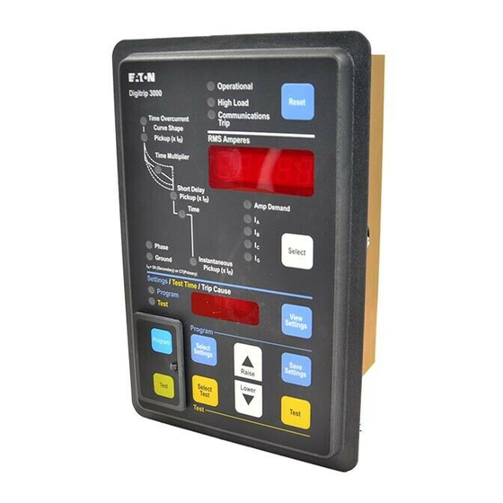
Direct reading displays indicate the value currently being discriminator can be disabled. considered, while multi-colored LED’s indicate operational conditions and specific functions. Fig. 1-2 Digitrip 3000 Protective Relay (Rear and Side Views) For more information visit: www.cutler-hammer.eaton.com Supersedes I.B. 17555C dated November 1999... - Page 9 This type of information is referred to • ANSI Curves (3 shapes per ANSI C37.112) as “COMMUNICATED INFORMATION”. - Moderately Inverse Fig. 1-4 Digitrip 3000 Curve Shape Possibilities For more information visit: www.cutler-hammer.eaton.com Supersedes I.B. 17555C dated November 1999...
-
Page 10: Standards
Example: ANSI and lEC curves using I Execution of circuit breaker “Close” and “Trip” commands Ct Rating = 1200A “Reset” of the relay after a trip = Pickup Current = 1800A Downloading of settings For more information visit: www.cutler-hammer.eaton.com Supersedes I.B. 17555C dated November 1999... -
Page 11: 2-1.3 Time Setting
1.6, 1.7, 1.8, 1.9, 2.0, 2.1, 2.2, 2.3, 2.4, 2.5, 2.6, 2.7, 2.8, 2.9, 3.0, 3.1, 3.2, 3.3, 3.4, 3.5, 3.6, 3.7, 3.8, 3.9, 4.0, 4.1, 4.2, 4.3, 4.4, 4.5, 4.6, 4.7, 4.8, 4.9, 5.0 For more information visit: www.cutler-hammer.eaton.com Supersedes I.B. 17555C dated November 1999... - Page 12 0.100, 0.125, 0.150, 0.175, 0.200, 0.225, 0.250, 0.275, 0.300, + 5% 0.350, 0.400, 0.450, 0.500, 0.550, 0.600, 0.650, 0.700, 0.750, 0.800, 0.850, 0.900, 0.950, 1.00, 1.25, 1.50, 1.75, 2.00, NONE For more information visit: www.cutler-hammer.eaton.com Supersedes I.B. 17555C dated November 1999...
- Page 13 Curve # Available Settings 0.05, 0.10, 0.15, 0.20, 0.25, 0.30, 0.35, 0.40, 0.45, 0.50, 0.55, 0.60, + 0.05 seconds SC-5403-92B 0.65, 0.70, 0.75, 0.80, 0.85, 0.90, 0.95, 1.00, 1.25, 1.50 For more information visit: www.cutler-hammer.eaton.com Supersedes I.B. 17555C dated November 1999...
- Page 14 (Program with Breaker Open Only) (Standard Relay Configuration – OC/Instantaneous) (Enable Remote Open/Close) (Communications Close) (Zone Interlocking Unlatched) (52b Breaker Input Mode) (Disable Download Set Points) (Manual Reset) Reserved For more information visit: www.cutler-hammer.eaton.com Supersedes I.B. 17555C dated November 1999...
-
Page 15: 2-1.5 Integral Testing
“Communications Close” command. alarm also closes the Communications Close Relay Communications is accomplished from the relay to the master computer via a 115.2 kHz frequency carrier signal For more information visit: www.cutler-hammer.eaton.com Supersedes I.B. 17555C dated November 1999... - Page 16 (IBM computer end being the recommended location. compatible). Refer to Figure 2-1 for a typical communications wiring diagram. Ground shielding For more information visit: www.cutler-hammer.eaton.com Supersedes I.B. 17555C dated November 1999...
- Page 17 LAST DEVICE IN NETWORK, TIE BACK SHIELD AND TAPE. WHEN TOC SWITCH IS USED, DOWNLOADING OF PROTECTION SETTINGS FROM THE COMPUTER WILL NOT BE POSSIBLE WITH BREAKER IN THE “TEST” POSITION. For more information visit: www.cutler-hammer.eaton.com Supersedes I.B. 17555C dated November 1999...
-
Page 18: Protective Relay Hardware
The user should rms values. The ampere demand currents are the program the relay before putting it into service, as averaged RMS values sensed over a 5-minute period of For more information visit: www.cutler-hammer.eaton.com Supersedes I.B. 17555C dated November 1999... - Page 19 LED time overcurrent time set point is displayed in the Settings/Test Time/Trip Cause window. When the time RMS Amperes Window This window has a five digit numeric display and shows: For more information visit: www.cutler-hammer.eaton.com Supersedes I.B. 17555C dated November 1999...
-
Page 20: 2-2.2 Rear Access Panel
The 52a option has the benefit of properly reporting breaker state when the circuit breaker is racked out. For more information visit: www.cutler-hammer.eaton.com Supersedes I.B. 17555C dated November 1999... - Page 21 Terminals 9 and 10 will nominal control power is applied to the relay and no have this potential on them. internal errors are detected. For more information visit: www.cutler-hammer.eaton.com Supersedes I.B. 17555C dated November 1999...
-
Page 22: 2-2.3 External Hardware
With DIP Switch S3 in the “ON” position, voltage ranges outlined in “UL Testing and Specification this contact closes when the relay detects a need for the Summary.” For more information visit: www.cutler-hammer.eaton.com Supersedes I.B. 17555C dated November 1999... - Page 23 Short Delay Time: • Short Delay Setting: ±50ms (0.1 to 11) x I , None [45 settings] • Instantaneous Setting: (0.5 to 11) x I , None [33 settings] For more information visit: www.cutler-hammer.eaton.com Supersedes I.B. 17555C dated November 1999...
-
Page 24: Section 3: Operation
“Protection Off Alarm” relay will not energize. When all self checks are good, the “Protection characteristics of the relay are graphically represented by time-current characteristic curves shown in Figure 3-2. For more information visit: www.cutler-hammer.eaton.com Supersedes I.B. 17555C dated November 1999... - Page 25 This movement is also independent of the For more information visit: www.cutler-hammer.eaton.com Supersedes I.B. 17555C dated November 1999...
- Page 26 Note that the scope of protection offered by the Digitrip 3000 is a coordinated effort. This is especially true when a Fig. 3-1 Digitrip 3000 Time-Current Characteristic Curves For more information visit: www.cutler-hammer.eaton.com Supersedes I.B. 17555C dated November 1999...
- Page 27 DT3000 Instruction Leaflet I.B. 17555D Effective: Date 07/02 Page 23 Fig. 3-2 Digitrip 3000 Typical Wiring Diagram For more information visit: www.cutler-hammer.eaton.com Supersedes I.B. 17555C dated November 1999...
- Page 28 Even if the ground fault harmonic current is present. protection is disabled, a detectable ground current will still be displayed. Ground Fault Protection Fig. 3-3 Sample Electronic Trip Curves For more information visit: www.cutler-hammer.eaton.com Supersedes I.B. 17555C dated November 1999...
- Page 29 Fig. 3-6 Short Delay Setting Adjustment Fig. 3-7 Short Delay Time Adjustment For more information visit: www.cutler-hammer.eaton.com Supersedes I.B. 17555C dated November 1999...
-
Page 30: 3-3.2 Program Mode
After the Raise and/or Lower pushbuttons are used to Settings/ Test Time/Trip Cause window. arrive at the desired Phase Inverse Time Overcurrent Pickup, the Select Settings pushbutton can be pressed For more information visit: www.cutler-hammer.eaton.com Supersedes I.B. 17555C dated November 1999... -
Page 31: 3-3.3 Programming Overview
The next set point selection to be made is the Frequency. the next sequential step. The choices are 60Hz and 50Hz. When this selection is For more information visit: www.cutler-hammer.eaton.com Supersedes I.B. 17555C dated November 1999... -
Page 32: 3-3.4 Test Mode
Raise and Lower and Select Settings. The Test Mode is not intended for live primary current interruption, but periodic tests that verify the functional performance of the relay. To enter the Test Mode, open For more information visit: www.cutler-hammer.eaton.com Supersedes I.B. 17555C dated November 1999... -
Page 33: 3-4.1 Address And Baud Rate Settings
SECTION 4: APPLICATION CONSIDERATIONS 4-1 ZONE INTERLOCKING CAPABILITIES To minimize damage to the system, faults should be cleared as quickly as possible. Zone selective interlocking For more information visit: www.cutler-hammer.eaton.com Supersedes I.B. 17555C dated November 1999... - Page 34 Up to 10 Digitrip devices may be wired in parallel to provide a single upstream restraint signal. Only 1 Zone common used for both phase and ground. DO NOT CONNECT ZONE COMMON TO EARTH GROUND. Fig. 4-1 Connection Diagram for Typical Ground Zone Selective Interlocking For more information visit: www.cutler-hammer.eaton.com Supersedes I.B. 17555C dated November 1999...
- Page 35 Up to 10 Digitrip devices may be wired in parallel to provide a single upstream restraint signal. Only 1 zone common used for both phase and ground. DO NOT CONNECT ZONE COMMON TO EARTH GROUND. Fig. 4-2 Connection Diagram for Typical Phase Zone Selective Interlocking For more information visit: www.cutler-hammer.eaton.com Supersedes I.B. 17555C dated November 1999...
-
Page 36: Section 5: Installation, Startup And Testing
IMPACC. Place the Digitrip 3000 Protective Relay through the cutout The thermal curves are only used for system in the panel. Be sure the Operator Panel faces outward. coordination. For more information visit: www.cutler-hammer.eaton.com Supersedes I.B. 17555C dated November 1999... -
Page 37: Wiring
Digitrip 3000 and external equipment. The user makes this drawing. It may also be helpful to refer to the relay’s specific wiring diagram shown in Figure 3-1. An example of For more information visit: www.cutler-hammer.eaton.com Supersedes I.B. 17555C dated November 1999... -
Page 38: 5-5.1 Before Power Application
“Replacement” section below. For more information visit: www.cutler-hammer.eaton.com Supersedes I.B. 17555C dated November 1999... - Page 39 LOOSENED OR REMOVED. WITHOUT SUCH SUPPORT, THE PROTECTIVE RELAY COULD FALL OR THE PANEL COULD BE DAMAGED Step 6: Mount the replacement unit. Read the “Mounting” section of this document before attempting this. For more information visit: www.cutler-hammer.eaton.com Supersedes I.B. 17555C dated November 1999...
- Page 40 Between TB1 -13 and TB1 -14 Missing • • • Ground Zone Interlocking Check for Ground Zone Interlocking Figure 3-1 not Used and Jumper Jumper Between TB1 -11 and TB1 –12 Missing For more information visit: www.cutler-hammer.eaton.com Supersedes I.B. 17555C dated November 1999...
-
Page 41: Section 7: Time-Current Curves
Caution: When the Digitrip 3000 Protective Relay is Powered, it Supplies Voltage to the “b” Contacts SECTION 7: TIME-CURRENT CURVES 7-1 DIGITRIP 3000 INVERSE TIME OVERCURRENT CURVES The following pages contain the specific time-current curves applicable to the Digitrip 3000 Protective Relay. For more information visit: www.cutler-hammer.eaton.com Supersedes I.B. 17555C dated November 1999... - Page 42 Overcurrent Time of 40 s @ 3 x makes T> 10000 s 100.00 40 Seconds at 3 per Unit 10.00 5 Seconds at 3 per Unit 1.00 0.2 Seconds at 3 per Unit 0.10 0.01 Multiple of In (I/I For more information visit: www.cutler-hammer.eaton.com Supersedes I.B. 17555C dated November 1999...
- Page 43 Overcurrent Time of 40 s @ 3 x makes T> 10000 s 100.00 40 Seconds at 3 per Unit 10.00 5 Seconds at 3 per Unit 1.00 0.2 Seconds at 3 per Unit 0.10 0.01 Multiple of In (I/I For more information visit: www.cutler-hammer.eaton.com Supersedes I.B. 17555C dated November 1999...
- Page 44 Minimum Trip Time is 0.05 s 100.00 40 Seconds at 3 per Unit 10.00 5 Seconds at 3 per Unit 1.00 0.2 Seconds at 3 per Unit 0.10 0.01 Multiple of In (I/I For more information visit: www.cutler-hammer.eaton.com Supersedes I.B. 17555C dated November 1999...
- Page 45 Minimum Trip Time is 0.05 s 100.00 40 Seconds at 3 per Unit 10.00 5 Seconds at 3 per Unit 1.00 0.2 Seconds at 3 per Unit 0.10 0.01 Multiple of In (I/I For more information visit: www.cutler-hammer.eaton.com Supersedes I.B. 17555C dated November 1999...
- Page 46 Minimum Trip Time is 0.05 s 100.00 40 Seconds at 3 per Unit 10.00 5 Seconds at 3 per Unit 1.00 0.2 Seconds at 3 per Unit 0.10 0.01 Multiple of In (I/I For more information visit: www.cutler-hammer.eaton.com Supersedes I.B. 17555C dated November 1999...
- Page 47 M in im u m T rip T im e is 0 .0 5 s 100.00 40 Seconds at 3 per Unit 10.00 5 Seconds at 3 per Unit 1.00 0.2 Seconds at 3 per Unit 0.10 0.01 Multiple of In (I/I For more information visit: www.cutler-hammer.eaton.com Supersedes I.B. 17555C dated November 1999...
- Page 48 Tolerance: Inverse Time Overcurrent Pickup is ±5% Inverse Time Overcurrent Time Multiplier is ±50 ms and –50 ms 100.00 10.00 2 Seconds 1.00 0.2 Seconds 0.10 0.01 Multiple of I Value For more information visit: www.cutler-hammer.eaton.com Supersedes I.B. 17555C dated November 1999...
- Page 49 Tolerance: Inverse Time Overcurrent Pickup is ±5% Inverse Time Overcurrent Time Multiplier is ±50 ms and –50 ms 100.00 10.00 2 Seconds 1.00 0.2 Seconds 0.10 0.01 Multiple of I Value For more information visit: www.cutler-hammer.eaton.com Supersedes I.B. 17555C dated November 1999...
- Page 50 Short Delay uses the O/C Contact 1000.00 100.00 Typical Inverse Time Overcurrent Function 10.00 Highest Pickup With Longest Time 1.00 0.10 Lowest Pickup With Shortest Time 0.01 Multiple of I Value For more information visit: www.cutler-hammer.eaton.com Supersedes I.B. 17555C dated November 1999...
- Page 51 Note: The Short Delay Time is used as the shortest tip time possible in Inverse Time Overcurrent or Short Delay 1000.00 100.00 Typical Inverse Time Overcurrent Function 10.00 Typical Short Delay Time Function 1.00 0.10 0.01 Multiple of I Value For more information visit: www.cutler-hammer.eaton.com Supersedes I.B. 17555C dated November 1999...
- Page 52 Tolerance: Instantaneous Setting is ±10% Instantaneous uses the Instantaneous Contact 1000.00 100.00 Ground, Lowest Setting Ground, Highest Setting 10.00 1.00 Phase, Lowest Setting Phase, Highest Setting 0.10 0.01 Multiple of I Value For more information visit: www.cutler-hammer.eaton.com Supersedes I.B. 17555C dated November 1999...
- Page 53 40 s @ 1 x makes T > 10000 s 100.00 40 Seconds at 1 per Unit 10.00 5 Seconds at 1 per Unit 1.00 0.2 Seconds at 1 per Unit 0.10 0.01 Multiple of In (I/I For more information visit: www.cutler-hammer.eaton.com Supersedes I.B. 17555C dated November 1999...
- Page 54 Minimum Trip Time is 0.05 s 100.00 40 Seconds at 1 per Unit 10.00 5 Seconds at 1 per Unit 1.00 0.2 Seconds at 1 per Unit 0.10 0.01 Multiple of In (I/I For more information visit: www.cutler-hammer.eaton.com Supersedes I.B. 17555C dated November 1999...
- Page 55 Minimum Trip Time is 0.05 s 100.00 40 Seconds at 1 per Unit 10.00 5 Seconds at 1 per Unit 1.00 0.2 Seconds at 1 per Unit 0.10 0.01 Multiple of In (I/I For more information visit: www.cutler-hammer.eaton.com Supersedes I.B. 17555C dated November 1999...
- Page 56 Tolerance: Inverse Time Overcurrent Pickup is ±5% Inverse Time Overcurrent Time Multiplier is +50ms or –50ms 100.00 10.00 Highest Pickup and Longest Time 1.00 Lowest Pickup and Shortest Time 0.10 0.01 Multiple of I Value For more information visit: www.cutler-hammer.eaton.com Supersedes I.B. 17555C dated November 1999...
- Page 57 Short Delay Time is +50ms or –50ms Short Delay uses the O/C Contact 100.00 10.00 Highest Pickup and Longest Time 1.00 0.10 Lowest Pickup and Shortest Time 0.01 Multiple of I Value For more information visit: www.cutler-hammer.eaton.com Supersedes I.B. 17555C dated November 1999...
- Page 58 Tolerance: Time Multiplier Tolerance is ± 10% or ± 0.09s, whichever is larger (>1.5 x I For Ground Pickup <0.2 : trip time tolerance is ±15% 100.00 10.00 Time Multiplier 1.00 0.10 0.01 Multiple of Pickup Current (I/I For more information visit: www.cutler-hammer.eaton.com Supersedes I.B. 17555C dated November 1999...
- Page 59 (> 1.5 x I For Ground Pickup < 0.2 : t rip t ime t olerance is ± 15% 100.00 10.00 Time Multiplier 1.00 0.10 0.01 Multiple of Pickup Current (I/I For more information visit: www.cutler-hammer.eaton.com Supersedes I.B. 17555C dated November 1999...
- Page 60 For Ground Pickup < 0.2 : trip time tolerance is ± 15% Minimum Trip Time is 2 pow er line cycles 100.00 10.00 Time Multiplier 1.00 0.10 0.01 Multiple of Pickup Current (I/I For more information visit: www.cutler-hammer.eaton.com Supersedes I.B. 17555C dated November 1999...
- Page 61 (>1.5 x I For Ground Pickup <0.2 : trip time tolerance is ±15% 100.00 10.00 Time Multiplier 1.00 0.15 0.10 0.05 0.01 Multiple of Pickup Current (I/I For more information visit: www.cutler-hammer.eaton.com Supersedes I.B. 17555C dated November 1999...
- Page 62 For Ground Pickup <0.2 : trip time tolerance is ±15% Minimum Trip Time is 2 power line cycles 100.00 10.00 1.00 Time Multiplier 0.10 0.15 0.05 0.01 Multiple of Pickup Current (I/I For more information visit: www.cutler-hammer.eaton.com Supersedes I.B. 17555C dated November 1999...
- Page 63 For Ground Pickup <0.2 : trip time tolerance is ±15% Minimum Trip Time is 2 power line cycles 100.00 10.00 1.00 0.10 Time Multiplier 0.05 0.15 0.01 Multiple of Pickup Current (I/I For more information visit: www.cutler-hammer.eaton.com Supersedes I.B. 17555C dated November 1999...
- Page 64 Figure 7-19 IEC-D Family Flat (SC-6691-96) 1000.00 Adjustable Time Multiplier (0.05………1.00) Tolerance: Time Multiplier Tolerance is ± 0.05 s, 100.00 10.00 Time Multiplier 1.00 0.15 0.05 0.10 0.01 Multiple of Pickup Current (I/I For more information visit: www.cutler-hammer.eaton.com Supersedes I.B. 17555C dated November 1999...
-
Page 65: Digitrip 3000 Curve Equations
ANSI XTRM Extremely Inverse 28.0 0.1217 IEC-A Normal Inverse 0.02 0.14 IEC-B Very Inverse 13.5 D = 0.05 to 1.0 step of 0.05 IEC-C Extremely Inverse IEC-D Definite Time For more information visit: www.cutler-hammer.eaton.com Supersedes I.B. 17555C dated November 1999... -
Page 66: A1.0 Introduction
This feature provides added security against false studs that protrude through the panel. tripping. For more information visit: www.cutler-hammer.eaton.com Supersedes I.B. 17555C dated November 1999... -
Page 67: A4.0 Wiring And Setup
Direct wire connections to the terminal blocks must be sizes #14 AWG to #10 AWG. The appropriate sized spade and ring lugs can also be used to accommodate the wires. For more information visit: www.cutler-hammer.eaton.com Supersedes I.B. 17555C dated November 1999... - Page 68 Protective Relay Power Supply Input. . Term. 17/19 AC 120-240 Vac, 50/60 Hz DC 48-250 Vdc Caution - Refer to Instruction Leaflet Fig. A-3 Rear View of DT3001 Drawout Enclosure For more information visit: www.cutler-hammer.eaton.com Supersedes I.B. 17555C dated November 1999...
- Page 69 FIG. A-4 DIGITRIP 3001 TYPICAL AC OR DC SCHEMATIC FIG. A-5 DIGITRIP 3001 TYPICAL AC EXTERNAL FIG. A-6 DIGITRIP 3001 TYPICAL RESIDUAL GROUND CURRENT CONNECTION WITH ZERO SEQUENCE CONNECTION GROUND CT For more information visit: www.cutler-hammer.eaton.com Supersedes I.B. 17555C dated November 1999...
- Page 70 Instruction Leaflet DT3000 I.B. 17555D Page 66 Effective: Date 07/02 Fig. A-7 Digitrip 3001 Typical Wiring Diagram For more information visit: www.cutler-hammer.eaton.com Supersedes I.B. 17555C dated November 1999...
-
Page 71: A5.0 Application Considerations
DRAWOUT ENCLOSURE FOR PROPER OPERATION OF THE DEVICE. When the unit is seated properly, the quick release buttons at the top and bottom of the unit will return to their non- For more information visit: www.cutler-hammer.eaton.com Supersedes I.B. 17555C dated November 1999... -
Page 72: A6.2 Removing The Relay
EXPOSES LIVE PARTS, WHERE THE HAZARD OF A FATAL ELECTRIC SHOCK IS PRESENT. ALWAYS DISCONNECT ANY CONTROL OR SOURCE POWER BEFORE TOUCHING ANYTHING ON THE INTERNAL OR EXTERNAL PARTS OF THE DRAWOUT OUTER CASE. For more information visit: www.cutler-hammer.eaton.com Supersedes I.B. 17555C dated November 1999... -
Page 73: B1.0 Introduction
• Powers the relay from nominal 120 Vac, 50/60Hz (DT3010 model) or 240 Vac, 50/60Hz (DT3020 model) Fig. B-1 Digitrip 3000 with DSPS For more information visit: www.cutler-hammer.eaton.com Supersedes I.B. 17555C dated November 1999... - Page 74 (0.1 to 2.0) in I [26 settings] • Short Delay Setting: (0.1 to 11) x I , None [45 settings] • Instantaneous Setting: (0.5 to 11) x I , None [33 settings] For more information visit: www.cutler-hammer.eaton.com Supersedes I.B. 17555C dated November 1999...
-
Page 75: B3.0 Functional Description
NOTE: There will be no effect to the DT3000 relay trip the panel. time accuracy when the Dual-Source Power Supply For more information visit: www.cutler-hammer.eaton.com Supersedes I.B. 17555C dated November 1999... - Page 76 Instruction Leaflet DT3000 I.B. 17555D Page 72 Effective: Date 07/02 Fig. B-2 Digitrip 3010/3020 Dimensions (Inches) For more information visit: www.cutler-hammer.eaton.com Supersedes I.B. 17555C dated November 1999...
-
Page 77: B5.0 Wiring And Setup
Ct ratio should be chosen so that normal full loading of the protected feeder corresponds to a secondary current of approximately one per unit or 5A secondary. For more information visit: www.cutler-hammer.eaton.com Supersedes I.B. 17555C dated November 1999... - Page 78 Fig. B-3 Digitrip 3010/3020 Protective Relay Typical AC Schematic FIG. B-4 DIGITRIP 3010/3020 TYPICAL AC FIG. B-5 DIGITRIP 3010/3020 TYPICAL RESIDUAL EXTERNAL CURRENT CONNECTION WITH ZERO GROUND CONNECTION SEQUENCE GROUND CT For more information visit: www.cutler-hammer.eaton.com Supersedes I.B. 17555C dated November 1999...
-
Page 79: B6.4 Burden Data
A, avoid applying it for a long period. Repeat step 3 for Phase B. Repeat steps 3 for Phase C, however, this time, use an isolated ac multi-meter to measure the voltage For more information visit: www.cutler-hammer.eaton.com Supersedes I.B. 17555C dated November 1999... - Page 80 Vac, 3 Phase I Total Burden, with ο Vac, 1 Phase I Total Burden, No Vac, 1 Phase I Fig. B-6 Digitrip 3010/3020 Protective Relay Burden Curves - OHMS For more information visit: www.cutler-hammer.eaton.com Supersedes I.B. 17555C dated November 1999...
- Page 81 No Vac, 3 Phase I Ct Voltage Drop, ο with Vac, 1 Phase I Ct Voltage Drop, No Vac, 1 Phase I Fig. B-8 Digitrip 3010/3020 Protective Relay Ct Voltage Drop Curves For more information visit: www.cutler-hammer.eaton.com Supersedes I.B. 17555C dated November 1999...
-
Page 82: For More Information Visit: Www.cutler-Hammer.eaton.com Supersedes I.b. 17555C Dated November
I.B. 17555D Page 78 Effective: Date 07/02 DSPS Output - True 3 Phase Current Only DSPS Output - 1 Phase Current Only Fig. B-9 DSPS Output Voltage to Relay For more information visit: www.cutler-hammer.eaton.com Supersedes I.B. 17555C dated November 1999... - Page 83 MERCHANTABILITY, OR WARRANTIES ARISING FROM COURSE OF DEALING OR USAGE OF TRADE, ARE MADE REGARDING THE INFORMATION, RECOMMENDATIONS AND DESCRIPTIONS CONTAINED HEREIN. Eaton Corporation Cutler-Hammer business unit 1000 Cherrington Parkway Moon Township, PA 15108-4312 www.cutler-hammer.eaton.com I.B. 17555D / Style # 8163H25H06...
Need help?
Do you have a question about the Digitrip 3000 series and is the answer not in the manual?
Questions and answers