Table of Contents
Advertisement
Advertisement
Table of Contents

Related Manuals for Ubiquiti PowerBeam M5 PBE-M5-620


Summary of Contents for Ubiquiti PowerBeam M5 PBE-M5-620
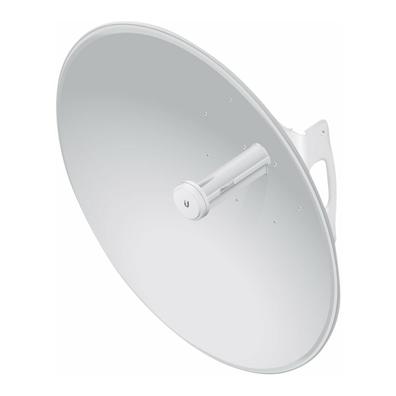
- Page 1 High-Performance Integrated InnerFeed ™ airMAX Bridge ® Model: PBE-M5-620...
-
Page 2: Package Contents
Wall-Mount Bracket Cord Guide TERMS OF USE: Ubiquiti radio devices must be professionally installed. Shielded Ethernet cable and earth grounding must be used as conditions of product warranty. TOUGHCable ™ is designed for outdoor installations. It is the customer’s responsibility to follow local country regulations, including operation within legal frequency channels, output power, and Dynamic Frequency Selection (DFS) requirements. -
Page 3: Bottom View
Hardware Overview Bottom View Antenna Feed Technology Ethernet Port Reset Button Release Button Dish Reflector Mounting Bracket Alignment Pins Rear Housing Release Button Slot Cable Door Reset Button To reset to factory defaults, press and hold the Reset button for more than 10 seconds while the PowerBeam is already powered on. -
Page 4: Leds
LEDs Signal The default values (from left to right) are shown below: LED will light blue when the wireless signal strength is equal to or above -65 dBm. LED will light blue when the wireless signal strength is equal to or above -73 dBm. LED will light blue when the wireless signal strength is equal to or above -80 dBm. -
Page 5: Installation Requirements
AC ground of the PoE. We recommend that you protect your networks from the most brutal environments and devastating ESD attacks with industrial-grade shielded Ethernet cable from Ubiquiti Networks. For more details, visit www.ubnt.com/toughcable Installation 1. Line up the Alignment Pins of the Rear Housing with the alignment holes of the Dish Reflector. - Page 6 3. Attach the Antenna Feed: a. I nsert the Antenna Feed into the Rear Housing, and push until it locks into place with a click. b. Lightly pull the Antenna Feed to ensure that it is locked into place and the Release button is fully engaged. Release Button Bottom View 4.
- Page 7 5. Attach two Hex Head Bolts, two Lock Washers, and two Flat Washers to the bottom of the Mounting Bracket. Ensure that there is a gap of 8 mm between each Flat Washer and the Mounting Bracket. Ensure that each Lock Washer is always Note: installed between the Hex Head Bolt and Flat Washer.
- Page 8 6. Attach the horizontal slot of the Support Arm to the Upper Pole Bracket using a Hex Head Bolt, Lock Washer, and Flat Washer. Ensure that the degree settings are the same Note: on both arms of the Upper Pole Bracket. Degree markings facing outward 7.
- Page 9 8. Each M8x150 Carriage Bolt includes a serrated flange nut. Remove these and use them in the next step. 9. Attach one Pole Clamp to each pole bracket. a. Insert two M8x150 Carriage Bolts into each pole bracket. b. Slide the hole of a Pole Clamp over one bolt of each pole bracket.
- Page 10 10. Each M10x100 Bolt includes a flat washer, lock washer, and nut. Remove these and use them to secure the bolts when assembling. 11. Attach the Stabilizer Brackets to the pole just beneath the area where the PowerBeam will be attached. Note: The pole-bracket assembly can accommodate a Ø...
- Page 11 12. Attach the pole-bracket assembly to the pole: a. Slide the slot of each Pole Clamp over the corresponding M8x150 Carriage Bolt. b. Tighten the serrated flange nuts of the bolts to secure the pole-bracket assembly to the pole. Proper slot orientation 25 N-m...
- Page 12 13. Lift the Dish Reflector and align the two lower Hex Head Bolts with the slots on the Lower Pole Bracket. Seat the bolts in the slots. 14. Attach each arm of the Upper Pole Bracket to the Mounting Bracket using a Hex Head Bolt, Lock Washer, and Flat Washer.
- Page 13 15. Before adjusting the tilt angle, ensure that the six Hex Head Bolts are loose enough to allow movement. If you cannot spin the washers freely by IMPORTANT: hand, then loosen the Hex Head Bolts until you can. 16. To adjust the tilt angle, turn the screw head of the elevation rod until the desired tilt is reached.
- Page 14 Steps 18-21 are optional instructions for mounting Note: the Gigabit PoE Adapter on a wall. 18. Remove the wall-mount bracket from the Gigabit PoE Adapter and position it at the desired location on the wall with the arrow pointing up. 19.
- Page 15 22. Connect the other end of the Ethernet cable from the PowerBeam to the Ethernet port labeled POE on the Gigabit PoE Adapter. 23. Connect an Ethernet cable from your LAN or computer to the Ethernet port labeled LAN on the Gigabit PoE Adapter. 24.
-
Page 16: Accessing Airos
Accessing airOS Verify connectivity in the airOS Configuration Interface. 1. Make sure that your host machine is connected via Ethernet to the PowerBeam. 2. Configure the Ethernet adapter on your host system with a static IP address on the 192.168.1.x subnet. 3. -
Page 17: Installer Compliance Responsibility
Since Ubiquiti Networks equipment can be paired with a variety of antennas and cables, the Antenna and Output Power fields are provided to the professional installer to assist in... -
Page 18: Specifications
Specifications PowerBeam PBE-M5-620 Dimensions 650 x 650 x 386 mm (25.6 x 25.6 x 15.2") Weight 6.4 kg (14.11 lb) Operating Frequency Worldwide: 5150 - 5875 MHz USA: 5725 - 5850 MHz Gain 29 dBi Networking Interface (1) 10/100/1000 Ethernet Port Enclosure Outdoor UV Stabilized Plastic Max. -
Page 19: Safety Notices
Safety Notices Read, follow, and keep these instructions. Heed all warnings. Only use attachments/accessories specified by the manufacturer. WARNING: Do not use this product in location that can be submerged by water. WARNING: Avoid using this product during an electrical storm. -
Page 20: Limited Warranty
(VI) has no original Ubiquiti MAC label, or is missing any other original Ubiquiti label(s); or (VII) has not been received by Ubiquiti within 30 days of issuance of the RMA. -
Page 21: Limitation Of Liability
SUBJECT TO LIMITATIONS, INTERRUPTIONS, DELAYS, CANCELLATIONS AND OTHER PROBLEMS INHERENT IN THE USE OF COMMUNICATIONS FACILITIES. UBIQUITI NETWORKS, ITS AFFILIATES AND ITS AND THEIR THIRD PARTY PROVIDERS ARE NOT RESPONSIBLE FOR ANY INTERRUPTIONS, DELAYS, CANCELLATIONS, DELIVERY FAILURES, DATA LOSS, CONTENT CORRUPTION, PACKET LOSS, OR OTHER DAMAGE RESULTING FROM ANY OF THE FOREGOING. - Page 22 Note Some countries, states and provinces do not allow exclusions of implied warranties or conditions, so the above exclusion may not apply to you. You may have other rights that vary from country to country, state to state, or province to province. Some countries, states and provinces do not allow the exclusion or limitation of liability for incidental or consequential damages, so the above limitation may not apply to you.
-
Page 23: Industry Canada
This radio transmitter FCC ID: SWX-PBE5M has been approved by FCC to operate with the antenna types listed below with the maximum permissible gain and required antenna impedance for each antenna type indicated. Antenna types not included in this list, having a gain greater than the maximum gain indicated for that type, are strictly prohibited for use with this device. -
Page 24: Rf Exposure Warning
Les utilisateurs devraient également noter que radars haute puissants sont alloués comme principaux utilisateurs (c’est-à-dire les utilisateurs de priorité) des bandes et 5650 à 5850 MHz et que ces radars pourraient causer des interférences ou dommages aux dispositifs LAN. Cet émetteur radio (IC: 6545A-PBE5M) a été... - Page 25 RoHS/WEEE Compliance Statement English European Directive 2002/96/EC requires that the equipment bearing this symbol on the product and/or its packaging must not be disposed of with unsorted municipal waste. The symbol indicates that this product should be disposed of separately from regular household waste streams.
- Page 26 Español La Directiva 2002/96/CE de la UE exige que los equipos que lleven este símbolo en el propio aparato y/o en su embalaje no deben eliminarse junto con otros residuos urbanos no seleccionados. El símbolo indica que el producto en cuestión debe separarse de los residuos domésticos convencionales con vistas a su eliminación.
-
Page 27: Declaration Of Conformity
UBIQUITI NETWORKS device, megfelel a vonatkozó alapvetõ [Hungarian] követelményeknek és az 1999/5/EC irányelv egyéb elõírásainak. Íslenska Hér me l sir UBIQUITI NETWORKS yfir ví a UBIQUITI NETWORKS device, er í samræmi vi grunnkröfur og a rar kröfur, sem ger ar eru í [Icelandic] tilskipun 1999/5/EC. -
Page 28: Online Resources
. u b n t . c o m ©2014-2015 Ubiquiti Networks, Inc. All rights reserved. Ubiquiti, Ubiquiti Networks, the Ubiquiti U logo, the Ubiquiti beam logo, airMAX, airOS, InnerFeed, PowerBeam, and TOUGHCable are trademarks or registered trademarks of Ubiquiti Networks, Inc.
Need help?
Do you have a question about the PowerBeam M5 PBE-M5-620 and is the answer not in the manual?
Questions and answers