Table of Contents
Advertisement
Quick Links
Advertisement
Table of Contents

Related Manuals for DMP Electronics XT30INT


Summary of Contents for DMP Electronics XT30INT
- Page 1 INSTALLATION GUIDE XT30INT SERIES CONTROL PANEL...
- Page 2 MODEL XT30INT CONTROL PANEL INSTALLATION GUIDE © 2018 Digital Monitoring Products, Inc. Information furnished by DMP is believed to be accurate and reliable. This information is subject to change without notice. Digital Monitoring Products XT30INT Series International Installation Guide...
-
Page 3: Table Of Contents
Replacement Period .................... 7 6.4 Discharge/Recharge .................... 7 6.5 Battery Supervision ..................... 7 XT30INT Power Requirements ................7 XT30INT Standby Battery Calculations ..............8 Bell Output .................... 9 Terminals 5 and 6 ....................9 Keypad Data Bus ................... 9 8.1 Description ......................9 8.2... - Page 4 ETHERNET LEDs ....................12 RESET Header ..................13 15.1 Description ......................13 Flash LOAD Jumper ................14 16.1 Description ......................14 Cellular Connections ................14 17.1 Cellular ......................14 Troubleshooting .................. 15 18.1 Troubleshooting Section ..................15 18.2 Common LCD Keypad Displays ................15 Digital Monitoring Products XT30INT Series Installation Guide...
-
Page 5: Panel Specifications
• XT50INT has 16 additional onboard wireless zones numbered 80, 85-99 Outputs The XT30INT panels provide four open collector outputs rated for 50 mA each. A Model 300 Output Harness is required. The open collector outputs provide the ground connection for a positive voltage source. -
Page 6: Introduction
Electrostatic Discharge (ESD) that can damage system components. Remove All Power From the Panel! Remove all AC and Battery power from the panel before installing or connecting any modules, cards, or wires to the panel. Digital Monitoring Products XT30INT Series Installation Guide... -
Page 7: System Components
This transient protection provides additional resistance to electrical surges such as lighting. Accessory Devices Cellular Communicator Cards 263HINT HSPA + Cellular Allows you to connect the XT30INT Series to any compatible HSPA+/SMS network. Communicator Card Zone and Output Expansion Modules 710 Bus Splitter/Repeater Increases keypad wiring distance to 2500 feet. -
Page 8: Xt30Int Series International Wiring Diagram
SYSTEM COMPONENTS XT30INT Series International Wiring Diagram 24.13W x 10.5H cm 50mV Digital Monitoring Products XT30INT Series Installation Guide... -
Page 9: Installation
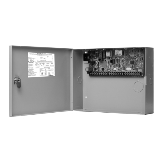
Phone Line Accessory Ethernet Modules Reset Programming Dual 1 3/4" and 1 3/8" Conduit Knockouts * 349AINT Optional Knockout Tamper Switch for 349AINT Attack Resistant Enclosure Battery Shelf Figure 3: Optional 349AINT Enclosure Digital Monitoring Products XT30INT Series Installation Guide... -
Page 10: Mounting Keypads
Never share the transformer output with any other equipment. Power LED When either AC transformer power or DC battery power is connected to the panel the PWR LED shows steady green. Digital Monitoring Products XT30INT Series Installation Guide... -
Page 11: Secondary Power Supply
Use 12 VDC sealed lead-acid rechargeable battery. Batteries supplied by DMP have been tested to ensure proper charging with DMP products. GEL CELL BATTERIES CANNOT BE USED WITH THE XT30INT SERIES INTERNATIONAL PANEL. Earth Ground Terminal 4 of the panel must be connected to earth ground using 14 gauge or larger wire to provide proper transient suppression. -
Page 12: Xt30Int Standby Battery Calculations
INSTALLATION XT30INT Standby Battery Calculations Standby Battery Power Calculations Alarm Current XT30INT International Panel 205mA ______mA 205mA ______mA Built-in Network (additional current) 145mA ______ 145mA ______ Active Zones 1-9 1.6mA ______ *2mA ______ Active Zone 10 ______ Qty ______ 30mA ______ 2-Wire Smoke Detectors 0.1mA ______ Qty ______ 0.1mA... -
Page 13: Bell Output
Terminals 7, 8, 9, and 10 of the panel are designated as the keypad data bus. In addition to keypads, the XT30INT International allows the connection of any combination of zone expansion modules, Glassbreak Detectors, and PIRs to the keypad bus up to the maximum of eight devices. -
Page 14: Overcurrent Ovc Led
11. Burglary Zones 10.1 Description On XT30INT panels, terminals 12 to 24 are the nine burglary zones. For programming purposes, the zone numbers are 1 to 9. The zone configurations on terminals 12 to 24 are described below. Terminal... -
Page 15: Zone Response Time
A resettable 2-wire Class B powered zone is provided on terminals 25 (positive) and 26 (negative) of the panel. For programming purposes, the zone number is 10 on the XT30INT International. The zone uses a Model 309, 3.3k Ohm EOL resistor (provided with the panel) and has an operating range of 8.8 to 13.9 VDC. -
Page 16: Phone Line Rj Connector
The two LEDs, located on the left side of the ETHERNET Connector, indicate network operation. The top, Link LED is a steady green light when an ethernet cable is connected. The bottom, Activity LED flashes yellow to indicate messages are being received or transmitted. Digital Monitoring Products XT30INT Series Installation Guide... -
Page 17: Reset Header
The RESET header is located just above the terminal strip on the right side of the circuit board and is used to reset the XT30INT Series International microprocessor. To reset the panel when first installing the system, install the reset jumper before applying power to the panel. After connecting the AC and battery, remove the reset jumper. -
Page 18: Flash Load Jumper
Flash LOAD Jumper 16.1 Description The XT30INT Series panel software can be updated via the panel’s programming (PROG) header. To update the panel with a new software version, complete the following steps at the protected premise: 1. Place a jumper across the RESET header and then remove the yellow and green wires from keypad bus terminals 8 and 9. -
Page 19: Troubleshooting
INSTALLATION Troubleshooting 18.1 Troubleshooting Section This section provides troubleshooting information for use when installing or servicing an XT30INT system. Problem Possible Cause Possible Solutions RESET Jumper is installed. Remove the RESET jumper. Open or short on the green data wire to Check for broken or shorted wires between Keypad displays “SYSTEM TROUBLE” the keypad. the panel and the keypad. Bad keypad or zone expander is affecting Replace keypad or zone expander. the Green data wire. - Page 20 International Certifications Intertek (ETL) Listed EN 50130-4:2011+A1:2014 Alarm systems. Electromagnetic compatibility. Product family standard: Immunity requirements for components of fire, intruder, hold up, CCTV, access control and social alarm systems. EN 50130-5:2011 Alarm systems. Environmental test methods. EN 50131-1:2006+A1:2009 Alarm systems. Intrusion and hold-up systems. System requirements. EN 50131-3:2009 Alarm systems.
Need help?
Do you have a question about the XT30INT and is the answer not in the manual?
Questions and answers