Advertisement
Quick Links
Advertisement

Subscribe to Our Youtube Channel
Related Manuals for Eaton DFDAP-M


Summary of Contents for Eaton DFDAP-M
- Page 1 Effective: March 2011 O & M Manual IM05805008K EATON DFDAP-M / FDAP-M Remote Alarm Panels...
- Page 2 EATON DFDAP-M / FDAP-M O & M Manual IM05805008K Remote Alarm Panels Effective: March 2011 TABLE OF CONTENTS INSTALLATION AND MOUNTING OF THE CONTROLLER ELECTRICAL CONNECTIONS ELECTRICAL CHECKOUT INSTRUCTIONS ELECTRIC ALARM PANELS 2.2.1 Pump Running check 2.2.2 Common Alarm check 2.2.3...
- Page 3 EATON DFDAP-M / FDAP-M O & M Manual IM05805008K Remote Alarm Panels Effective: March 2011 INSTALLATION & MAINTENANCE Incoming Normal power and Supervisory MANUAL FOR REMOTE ALARM (backup) power connections are clearly marked L PANELS and N and are located on the upper right side of the microprocessor board.
- Page 4 Remote Alarm Panels Effective: March 2011 2.1 Electrical Checkout Instructions (For Use with Eaton Remote Alarm Panels) WARNING:The following procedures should be carried out by a qualified electrician familiar with the electrical safety procedures associated with this product and its associated equipment.
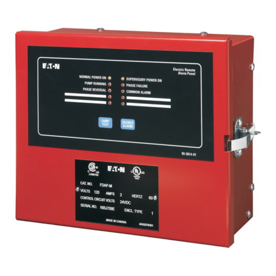
- Page 5 The FDAP-M electric remote alarm panel has four LED visual indicators to indicate Pump Running, Phase Failure, Common Alarm and Phase Reversal. The DFDAP-M diesel remote alarm panel also has four LED visual indicators that indicate Not in AUTO Mode, Engine Running, Common Alarm and Low Fuel.
- Page 6 EATON DFDAP-M / FDAP-M O & M Manual IM05805008K Remote Alarm Panels Effective: March 2011 Electrical Remote Alarm Panel - FDAP-M 11.56 [294] 15.49 [393] 9.75 [248] 9.55 [243] 8.00 [203] 0.27 [ 7]x4 WALL MTG. HOLES 4.74 [120] NOTE: 1.
- Page 7 EATON DFDAP-M / FDAP-M O & M Manual IM05805008K Remote Alarm Panels Effective: March 2011 Diesel Engine Remote Alarm Panel - DFDAP-M 11.56 [294] 15.49 [393] 9.75 [248] 9.55 [243] 8.00 [203] 0.27 [ 7]x4 WALL MTG. HOLES 4.74 [120] NOTE: 1.
- Page 8 EATON DFDAP-M / FDAP-M O & M Manual IM05805008K Remote Alarm Panels Effective: March 2011 Wiring Schematic - Electric Remote Alarm Panel - FDAP-M N. Y. C. APPROVED FIGURE 3 EATON Corporation www.chfire.com...
- Page 9 EATON DFDAP-M / FDAP-M O & M Manual IM05805008K Remote Alarm Panels Effective: March 2011 Wiring Schematic - Diesel Remote Alarm Panel - FDAP-M N. Y. C. APPROVED FIGURE 4 EATON Corporation www.chfire.com...
- Page 10 Eaton Corporation 10725 - 25th Street NE Unit 124 Calgary , Alberta, Canada © 2011 Eaton Corporation 3N 0A4 All Rights Reserved Tel: +1-403-717-2000 Printed in Canada Fax: +1-403-717-0567 Publication No.: IM05805008K email: chcfirepump@eaton.com March 2011 www.chfire.com...
Need help?
Do you have a question about the DFDAP-M and is the answer not in the manual?
Questions and answers