Table of Contents
Advertisement
Quick Links
Advertisement
Table of Contents
Troubleshooting

Summary of Contents for Infinite TRANSTECTOR 700 AV/T Series
- Page 1 Series 700 AV/T Power Conditioner 60 K(I) Power Conditioner with Voltage Regulation (60 Hz) Owners Manual Important safety instructions - save these instructions and review prior to using equipment Designed for the Varian On Board Imager™ 60 k(I) 60 Hz Single Output 1402-001 Rev C...
-
Page 2: Table Of Contents
Quadruple Output Power Conditioner | Owners Manual TABLE OF CONTENTS Receiving and Inspecting the Unit General Description Theory of Operation Safety Precautions Preliminary Installation Input Wire Size, Grounding and Output Wiring Installation 11-15 Bypass Switch Start - up and Operation Preventive Maintenance Performance Checklist 19-20... -
Page 3: Receiving And Inspecting The Unit
RECEIVING & INSPECTING THE UNIT RECEIVING & INSPECTING THE UNIT INSPECTING THE POWER CONDITIONER INSPECTING THE POWER PROCESSOR Upon receipt of the unit, visually inspect for shipping damage. If any damage is found, the Purchaser must contact the Carrier immediately and file a shipping damage claim. Upon receipt of the unit, visually inspect for shipping damage. - Page 4 Quadruple Output Power Conditioner | Owners Manual RECEIVING & INSPECTING THE UNIT (continued) RECEIVING & INSPECTING THE UNIT - CONTINUED REMOVING THE POWER CONDITIONER FROM PALLET REMOVING THE POWER PROCESSOR FROM PALLET 60K(i) REMOVE LAG BOLTS (TYPICAL BOTH SIDES) LIFT HERE WITH REMOVE UNIT PALLET JACK...
-
Page 5: General Description
GENERAL DESCRIPTION The Series 700 AV/T Power Conditioner is a continuous duty power line conditioner designed to supply reliable, clean regulated power to critical loads. An efficient design with state of the art micro- processor controlled solid state devices provide immunity to all line disturbances. The basic design consists of a three phase triple shielded isolation transformer with seven separate voltage taps per phase. - Page 6 Quadruple Output Power Conditioner | Owners Manual GENERAL DESCRIPTION (continued) OPERATION The Series 700AV/T Power Conditioner is operated by simply turning on the main AC input circuit breaker. As an option, units may have a bypass switch. This is a no load switch and MUST only be operated when the unit is OFF.
-
Page 7: Theory Of Operation
THEORY OF OPERATION The Series 700AV/T Power Line Conditioner provides the triple function of isolation, noise attenuation and voltage regulation. The first two functions are provided by the power transformer, where as the third function of voltage regulation is achieved through solid state thyristors (SCR’s) connected to taps on the power transformer. -
Page 8: Safety Precautions
Quadruple Output Power Conditioner | Owners Manual SAFETY PRECAUTIONS SAFETY PRECAUTIONS *****************WARNING***************** THERE ARE DANGEROUSLY HIGH VOLTAGES PRESENT WITHIN THE ENCLOSURE OF THE POWER SUPPLY SYSTEM. CAUTION MUST BE TAKEN WHEN WORKING WITH THE SYSTEM. IT IS RECOMMENDED THAT ALL WORK BE PERFORMED BY QUALIFIED ELECTRICAL PERSONNEL ONLY. -
Page 9: Preliminary Installation
PRELIMINARY INSTALLATION INSTALLATION CONSIDERATIONS Prior to installing the Series 700A/VS, be sure to take into consideration the site you have selected. Power Conditioners produce heat and therefore require ventilation as well as accessibility. Consider these factors. ƒ Ventilation ƒ Proper Ground Techniques ƒ... -
Page 10: Input Wire Size, Grounding And Output Wiring
Quadruple Output Power Conditioner | Owners Manual INPUT WIRE SIZE, GROUNDING AND OUTPUT WIRING UNIT CONTINUOUS OUTPUT KVA INPUT MAX OUTPUT CURRENT CONTINOUS BREAKER SIZE 60 K(I) 30 kVA 110 A for 208 V 36 A continuous for 480 V 100 for 240 V 72 A intermittent for 480 V 60 for 480 V... -
Page 11: Installation
INSTALLATION 60K(I) INSTALLATION Before installing the Power Processor make sure that the input voltage and the output voltages match the unit’s specification plate. CLEARANCES, INPUT WIRE SIZE, GROUNDING AND OUTPUT WIRING CLEARANCES, INPUT WIRE SIZE, GROUNDING AND OUTPUT WIRING The following pages show the locations of the conduit landings and input/output terminals, plus any clearances The following pages show the locations of the conduit landings and input/output terminals, plus any required in the installation. - Page 12 Quadruple Output Power Conditioner | Owners Manual 60K(i) INSTALLATION 60K(I) INSTALLATION CABINET CLEARANCES - 60K(I) CABINET CLEARANCES - 60K(i) 4" 4" PAGE 15...
- Page 13 60K(I) INSTALLATION (continued) 60K(i) INSTALLATION CONTINUED CABINET CLEARANCES - 60K(I) CABINET CLEARANCES - 60K(i) TO REMOVE TOP: REMOVE RETAINING SCREW IN REAR OF TOP, LIFT REAR, & SLIDE FORWARD. TO REMOVE SIDE: REMOVE RETAINING SCREW IN TOP OF PANEL, & BOTTOM SIDE. LIFT PANEL OFF. 4.000 4.000 ENVIRONMENTAL...
- Page 14 60K(i) INSTALLATION CONTINUED Quadruple Output Power Conditioner | Owners Manual INPUT & OUTPUT CONNECTIONS - 60K(i) 60K(I) INSTALLATION (continued) INPUT & OUTPUT CONNECTIONS - 60 K(I) Input and output terminals are located at the front of the unit. 1. Input and output terminals are located at the front of the unit. To access terminal blocks, remove conduit panels and any other panels necessary on the front of the unit.
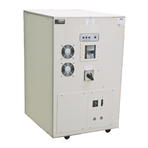
- Page 15 60K(i) INSTALLATION CONTINUED 60K(I) INSTALLATION (continued) INPUT & OUTPUT CONNECTIONS - 60 K(I) INPUT & OUTPUT CONNECTIONS - 60K(i) 21.500 "ALERT" OUTPUT ALERT SUPERIOR SURGE SUPPRESSION LIGHT COOLING CONDITIONED POWER FANS "ON" LIGHTS INPUT CIRCUIT BREAKER 44.125 HOLE PROVIDED FOR 1.00 INPUT BY-PASS SWITCH CONDUIT HOLE PROVIDED...
-
Page 16: Bypass Switch
STORING If it is necessary to store the unit for a period of time before it is installed, be sure to place the unit in a clean, dry area. To prevent excessive dust from accumulating on the unit, it is advisable to protect it by replacing it in the Quadruple Output Power Conditioner | Owners Manual original container (if possible). -
Page 17: Start - Up And Operation
START - UP START-UP ***WARNING*** THERE ARE DANGEROUSLY HIGH VOLTAGES PRESENT WITHIN THE ENCLOSURE OF THE POWER SUPPLY SYSTEM. CAUTION MUST BE TAKEN WHEN WORKING WITH THE ENCLOSURE. IT IS RECOMMENDED THAT ALL WORK BE PERFORMED BY QUALIFIED ELECTRICAL PERSONNEL ONLY. NOTE: INITIAL START-UP SHOULD BE PERFORMED WITH NO LOAD ON SYSTEM. -
Page 18: Preventive Maintenance
Quadruple Output Power Conditioner | Owners Manual PREVENTIVE MAINTENANCE PREVENTIVE MAINTENANCE ***WARNING*** DANGER OF ELECTRICAL SHOCK, TURN OFF ALL POWER SUPPLYING THIS EQUIPMENT PRIOR TO MAINTENANCE. To ensure longer component life and trouble-free operation, minor preventive maintenance procedures should be performed at regular intervals, for example once every year. -
Page 19: Performance Checklist
PERFORMANCE CHECKLIST Company______________________________________________________________ Model #____________________________ Serial #__________________ 1. Customer Comments or Problems____________________________________ 2. Power Conditioner Environment Clean and Dust Free Yes No 3. Phase Rotation Correct (ABC) Yes_______ No________ 4. Electrically wired properly ie...Conductor Sizing, Breakers, Grounding 5. Verify Input Voltage (See spec. tag) 6. - Page 20 Quadruple Output Power Conditioner | Owners Manual PERFORMANCE CHECKLIST (continued) 9. Input/Output Voltage Checks (Adjust as Needed). No Load Input No Load Output A-B__________VAC__________ A-N__________ VAC A-B__________VAC B-C__________VAC__________ B-N__________ VAC B-C__________VAC A-C__________VAC__________ C-N__________ VAC A-C__________VAC 10. Available Load Input Available Load Output A-B__________VAC__________ A-N__________VAC A-B__________VAC...
-
Page 21: General Troubleshooting
GENERAL TROUBLESHOOTING GENERAL TROUBLESHOOTING ***WARNING*** THERE ARE DANGEROUSLY HIGH VOLTAGES PRESENT WITHIN THE ENCLOSURE OF THE POWER SUPPLY SYSTEM. UNDER NO CIRCUMSTANCES SHOULD ANY PERSON REACH WITHIN THE ENCLOSURE OF THIS EQUIPMENT. ALL SERVICE TO THIS PIECE OF EQUIPMENT SHOULD BE PERFORMED BY QUALIFIED PERSONNEL ONLY. SYMPTOM PROBABLE CAUSES 1. - Page 22 Quadruple Output Power Conditioner | Owners Manual GENERAL TROUBLESHOOTING TROUBLESHOOTING (continued) ***WARNING*** THERE ARE DANGEROUSLY HIGH VOLTAGES PRESENT WITHIN THE ENCLOSURE OF THE POWER SUPPLY SYSTEM. UNDER NO CIRCUMSTANCES SHOULD ANY PERSON REACH WITHIN THE ENCLOSURE OF THIS EQUIPMENT. ALL SERVICE TO THIS PIECE OF EQUIPMENT SHOULD BE PERFORMED BY QUALIFIED PERSONNEL ONLY.
- Page 23 TROUBLESHOOTING CONTINUED Correct and tighten any loose connections, replace any physically burned or broken components. TROUBLESHOOTING (continued) Check all fuses in system *. B. Correct and tighten any loose connections, replace any physically burned or broken components. C. Check all fuses in system *. Time delay fuses, semi-conductor fuses, fan fuses, circuit board fuses, SCR fusible Link wire.
- Page 24 TROUBLESHOOTING CONTINUED Measure the following resistance on each power module. There are 7 per phase or 21 for all three Quadruple Output Power Conditioner | Owners Manual phases. *Refer to the circuit diagrams received with your unit. Note: When checking the power module assembly, if more than one defective power module is present TROUBLESHOOTING (continued) it will appear as if all the power modules are defective.
- Page 25 TROUBLESHOOTING (continued) CHECK THE SCR SNUBBER CARD 1. Three components make up the SCR snubber. (Resistors, MOVs and Capacitors). Check for open resistors. Check MOVs for shorts, they should read high resistance when ohm meter is placed across them. Resistance check each capacitor. The DC resistance across the snubber capacitor should look capacitive-that is high resistance after the meter charges the capacitor.
-
Page 26: Troubleshooting
Quadruple Output Power Conditioner | Owners Manual TROUBLESHOOTING (continued) TROUBLESHOOTING CONTINUED 6. Turn main AC on. With DC voltmeter on the millivolt scale check between TP1 and TP GND of the control card and adjust pot P2 so meter reads “0” millivolts or close as possible. Turn main AC on. - Page 27 TROUBLESHOOTING (continued) FINAL TESTING & ADJUSTMENT 1. Connect AC voltmeter to output of system with proper meter scale selected. NOTE: On 3 phase systems, connect your AC voltmeter across the output phase to neutral. 2. Disconnect customers loads. 3. Energize system. 4.
-
Page 28: Control Board Adjustments
Quadruple Output Power Conditioner | Owners Manual CONTROL BOARD ADJUSTMENTS CONTROL BOARD ADJUSTMENTS CONTROL BOARD ADJUSTMENTS (#414921) CONTROL BOARD ADJUSTMENTS (#414921) FIELD ADJUSTMENT PROCEDURE FIELD ADJUSTMENT PROCEDURE ***WARNING*** THERE ARE DANGEROUSLY HIGH VOLTAGES PRESENT WITHIN THE ENCLOSURE OF THE POWER SUPPLY SYSTEM. - Page 29 TROUBLESHOOTING CONTINUED Turn main AC on. With DC voltmeter on the millivolt scale check between TP1 and TP GND of the control card and adjust pot P2 so meter reads “0” millivolts or close as possible. NOTE: Refer to Appendix A Page A51 for test points and pot locations on control card. CONTROL BOARD ADJUSTMENTS (continued) Use the following formula to calculate the next adjustments.
-
Page 30: Over / Under Voltage Detection Adjustments
Quadruple Output Power Conditioner | Owners Manual OVER / UNDER VOLTAGE DETECTION ADJUSTMENTS OPTIONAL OVER/UNDER VOLTAGE DETECTION BOARD #35867 (See Appendix A - Page 40 for Board Layout) NOTE: Adjustments are referenced from the units output. UNDERVOLTAGE ADJUSTMENT 1. The under voltage adjustment can be adjusted from -1% (118.5 VAC) to -20% (95 VAC). The standard setpoint is -10% (108 VAC). -
Page 31: Parts List
PARTS LIST - 60K(I) 208V INPUT 240V INPUT 480V INPUT 600V INPUT DESCRIPTION PART # PART # PART # PART # 202504 202504 202504 203792 MAIN TRANSFORMER 16793 16794 104022 104027 MAIN INPUT BREAKER 18276 18276 18276 18276 FILTER CAPACITOR 17538 17538 17538... -
Page 32: Specifications
Quadruple Output Power Conditioner | Owners Manual SPECIFICATIONS - 60K(I) 1.0 SCOPE This specification covers the electrical characteristics of the 60 K(I) Power Conditioner which provides clean regulated power for Varian On Board Imager™ or peripherals. 2.0 GENERAL The Power Line Conditioner consists of an all copper, multiple tapped, triple shield isolation transformer. The low output impedance of the transformer in conjunction with the electrostatic shields assures precision hospital grade performance with excellent noise and transient attenuation. - Page 33 2.1.2 LISTINGS / COMPLIANCE ƒ The system shall be listed to UL/cUL standards UL1012 or ESA approved ƒ The system shall comply to: FCC Article 15, Section J, Class A and ƒ ANSI C62.14 (electromagnetic compatibility) 3.0 DYNAMIC ELECTRICAL CHARACTERISTICS 3.1 OPERATING VOLTAGE The input voltage shall be 208 VAC, 240 VAC, 480 VAC or 600 VAC input, three phase 60 Hz.
- Page 34 Quadruple Output Power Conditioner | Owners Manual 3.10 OPERATING FREQUENCY 60 Hertz ±3 Hertz 3.11 HARMONIC DISTORTION Less than 1 % THD added to the output waveform under any dynamic linear loading conditions presented to the line regulator. 3.12 TURN-ON CHARACTERISTICS When energized the voltage overshoot is 5 % or less of the nominal voltage for less than 1 cycle.
- Page 35 4.0 MAIN TRANSFORMER 4.1 BASIC CONSTRUCTION The transformer windings are of all copper conductor construction with separate primary and secondary isolated windings. 4.2 MAGNETIC Grain oriented, M6 grade, stress relieved silicon transformer steel is utilized to minimize losses and provide maximum efficiency. Flux density will not exceed 15 k gauss. 4.3 INSULATION Class N (200°...
- Page 36 Quadruple Output Power Conditioner | Owners Manual 8.0 CABINET 8.1 TERMINATION Termination is front access with input and output connections made of copper stand off bus. The unit is constructed using an isolation transformer and is considered to be a “separately derived system”.
- Page 37 Appendix A Relative Drawings and Schematics...
-
Page 38: Component Location Diagram
COMPONENT LOCATION DIAGRAM Quadruple Output Power Conditioner | Owners Manual COMPONENT LOCATION DIAGRAM 60K(i) APPENDIX PAGE A47... -
Page 39: Heat Sink Assembly Layout
HEAT SINK ASSEMBLY HEAT SINK ASSEMBLY LAYOUT 60K(i) SEMI-CONDCUCTOR FUSE SHUNT CABLE TO TRANSFORMER TAP WIRES FROM POWER TRANSFORMER GATE CONNECTIONS (K2-1 THROUGH K2-7 G1-1 THROUGH G1-7, CONNECTIONS) G2-1 THROUGH G2-7 (TYPICAL) (TYPICAL) THERMAL FUSIBLE SENSOR LINK HEAT SINK POWER MODULE APPENDIX PAGE A49... -
Page 40: Control Board Layout
CONTROL BOARD LAYOUT Quadruple Output Power Conditioner | Owners Manual CONTROL BOARD LAYOUT GRND 414921 115V 240V 208V APPENDIX PAGE A51... -
Page 41: Over/Under Board Layout
OVER/UNDER BOARD LAYOUT OVER/UNDER BOARD LAYOUT 35867 APPENDIX PAGE A52... -
Page 42: Circuit Diagram
Quadruple Output Power Conditioner | Owners Manual CIRCUIT DIAGRAM CIRCUIT DIAGRAM 60K(I) - (208, 240, 480 V Input) 60K(i) - (208, 240, 480V Input) APPENDIX PAGE A53... - Page 43 CIRCUIT DIAGRAM CIRCUIT DIAGRAM 60K(I) - (600 V Input) 60K(i) - (600V Input) APPENDIX PAGE A54...
-
Page 44: Cabinet Layout
Quadruple Output Power Conditioner | Owners Manual CABINET LAYOUT CABINET LAYOUT 60K(I) 60K(i) APPENDIX PAGE A57... - Page 45 CABINET LAYOUT CABINET LAYOUT 60K(I) 60K(i) APPENDIX PAGE A58...
- Page 46 Quadruple Output Power Conditioner | Owners Manual CABINET LAYOUT CABINET LAYOUT 60K(I) 60K(i) APPENDIX PAGE A59...
-
Page 47: Symbol Library
SYMBOL LIBRARY SYMBOL LIBRARY The following symbol indicates that caution should be taken when performing the process required in this manual. Damage to the unit or personal harm could happen if proper precautions are not taken. Caution The following symbol indicates that there is a risk of electrical shock if proper precautions are not followed.
Need help?
Do you have a question about the TRANSTECTOR 700 AV/T Series and is the answer not in the manual?
Questions and answers