
Related Manuals for Bender RFID113


Summary of Contents for Bender RFID113
- Page 1 Manual RFID113 For use in combination with charge controllers used in electric vehicle charging stations, wall boxes and street light charging points RFID113_D00303_00_M_XXEN/05.2018...
- Page 2 Bender GmbH & Co. KG P.O. Box 1161 • 35301 Grünberg • Germany Londorfer Strasse 65 • 35305 Grünberg • Germany Tel.: +49 6401 807-0 • Fax: +49 6401 807-259 E-Mail: info@bender.de • www.bender.de © Bender GmbH & Co. KG All rights reserved.
-
Page 3: Table Of Contents
Table of Contents 1. Important information ..................5 How to use this manual ................. 5 Technical support: service and support ........... 5 Delivery conditions ..................6 Inspection, transport and storage .............. 6 Disposal ....................... 6 Intended use ...................... 6 2. RFID module ..................... 8 Dimensions for mounting ................ -
Page 5: Important Information
This symbol denotes information intended to assist the user in making optimum use of the product. 1.2 Technical support: service and support Technical support by phone or e-mail for all Bender products. Questions concerning specific customer applications Commissioning ... -
Page 6: Delivery Conditions
Abide by the national regulations and laws governing the disposal of this de- vice. Ask your supplier if you are not sure how to dispose of the old equip- ment. For more information on the disposal of Bender devices, refer to our homepage at www.bender.de -> Service & support. - Page 7 Charging is initiated by holding a valid RFID card, which is registered to a backend system, close to the reader on the RFID module. Charging starts when the contactor in the charging system is switched on to provide power flow. In offline operation, the charge controller can optionally allow charging without authorization or it can authorize users based on RFID and a local white list of authorized RFID cards.
-
Page 8: Rfid Module
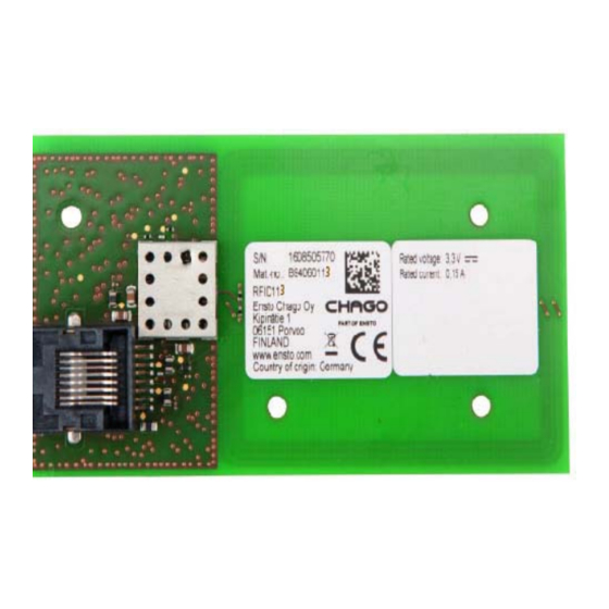
RFID module 2. RFID module The RFID module, shown below, contains a card reader . Socket for RJ45 cable The RFID module must be placed at a distance of at least 20 mm from any significant metal surface or metal parts to ensure optimum RFID reading performance. -
Page 9: Dimensions For Mounting
RFID module The RFID frequency is 13.56 MHz. The PN532 Near Field Communication (NFC) controller is used for contactless communication, which supports virtu- ally all RFID/NFC communication means on this frequency. Currently only pas- sive tags with a UID are read. Further functionality is possible upon request. The RFID module is connected to the charge controller via a standard RJ45 cable. -
Page 10: Operation
RFID module. The status of the charging system is shown by the 12 RGB LEDs on the LEDM100 module. The LEDM100 module is described in a separate operating manual, which can be downloaded from www.bender.de/manuals Charging can be terminated when the RFID card is again held in front of the charging system. 2.3 Integration The RFID module is integrated solely in conjunction with ICC1612 charge con- trollers under professional installation. -
Page 11: Rj45 Connector Pin Assignment
2.3.1 RJ45 connector pin assignment Pin number Description RX PN532 TX PN532 3.3 V 5 V (not used for the RFID functionality) RFID113_D00303_00_M_XXEN/05.2018... -
Page 12: Technical Data
Technical data 3. Technical data 3.1 Tabular data Insulation coordination acc. to IEC 60664-1/IEC 60664-3 Rated voltage ................................ 12.5 V Overvoltage category..............................III Pollution degree ................................3 Rated impulse withstand voltage........................... 800 V Rated insulation voltage............................12.5 V Altitude..............................≤ 2000 m AMSL Rated voltage/rated current Rated voltage ..............................DC 3.3 V Rated voltage tolerance............................ -
Page 13: Standards, Approvals, Certifications
Maximum read distance.............................100 mm Weight ..................................13 g 3.2 Standards, approvals, certifications The RFID module has been developed in compliance with: ISO14443A/MIFARE IEC 61851-1/-22 IEC 60950-1 3.3 Ordering information Type Art. No. RFID113 B94060113 RFID113_D00303_00_M_XXEN/05.2018... - Page 14 Technical data RFID113_D00303_00_M_XXEN/05.2018...
- Page 16 Bender GmbH & Co. KG P.O. Box 1161 • 35301 Gruenberg • Germany Londorfer Strasse 65 • 35305 Gruenberg • Germany Tel.: +49 6401 807-0 • Fax: +49 6401 807-259 E-Mail: info@bender.de • www.bender.de Group Photos: Bender archives...
Need help?
Do you have a question about the RFID113 and is the answer not in the manual?
Questions and answers