
Related Manuals for Bender RCMB131-02


Summary of Contents for Bender RCMB131-02
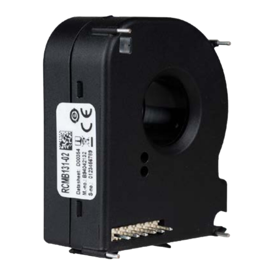
- Page 1 Manual EN RCMB131-02 AC/DC sensitive residual current monitoring module for measuring AC and DC currents up to ±100 mA RCMB131-02_D00354_01_XXEN / 05.2024...
-
Page 2: Intended Use
• Supply voltage DC 12…24 V Functional description The RCMB131-02 is used to measure residual currents and output the values via the PWM output. The residual current monitoring module measures both AC and DC currents. The RMS value is calculated from the DC component included in the residual current and the AC component below 2000 Hz. -
Page 3: Dimension Diagram
RCMB131-02 Dimension diagram Lötpins 42.7 34.2 Soldering pins 2.56 45.89 42.54 52.7 28.65 3.75 3.45 19.8 34.83 Rastermaß / Grid size 2.54 All dimensions in mm Installation and connection of an electric shock! Existing protective conductors and low-resistance conductor loops must not be routed through the measuring current transformer! Otherwise, high currents could be induced into the conduc- tor loop due to the AC/DC sensitive measuring technology used. -
Page 4: Wiring Diagram (Example)
RCMB131-02 Wiring diagram (example) RCMB131-02 RCMB131-02 Customer Controller The maximum cable length must be limited to ≤ 10 m. RCMB131-02_D00354_01_XXEN / 05.2024... - Page 5 RCMB131-02 Timing diagram “Functional test” M1…2 in the timing diagram are the points in time at which a higher-level control can and should check during the functional test that the switching output S1…actually switches. Possible causes for a failed functional test: •...
-
Page 6: Technical Data
RCMB131-02 Technical data Insulation coordination according to IEC 60664-1 Disturbances Primary circuit �������������������������������monitored primary conductors Load current I �����������������������������������������������������������������������32 A Secondary circuit �������������Connections Vcc, GND, T, PWM, S1, ERR Connection All following specifications apply to the insulation between the Max� Cable length �������������������������������������������������������������≤ 10 m... -
Page 7: Standards, Approvals, Certifications
RCMB131-02 Standards, approvals, certifications The specified standards take into account the edition valid until 05.2024 unless otherwise indicated. EU Declaration of Conformity The EU Declaration of Conformity is available at the following Internet address: https://www.bender.de/fileadmin/content/Products/CE/CEKO_RCMB13x.pdf Ordering details Type Measuring range Art. - Page 8 Alle Rechte vorbehalten. 35305 Grünberg Nachdruck und Vervielfältigung nur mit Germany Genehmigung des Herausgebers. © Bender GmbH & Co. KG, Germany Subject to change! The specified Tel.: +49 6401 807-0 All rights reserved. standards take into account the edition info@bender.de...
Need help?
Do you have a question about the RCMB131-02 and is the answer not in the manual?
Questions and answers