
Related Manuals for Bender RCMB330


Summary of Contents for Bender RCMB330
- Page 1 Manual RCMB330 AC/DC sensitive residual current monitoring module with integrated measuring current transformer Manual EN RCMB330_D00389_00_M_XXEN/12.2020...
- Page 2 Bender GmbH & Co. KG PO Box 1161 • 35301 Grünberg • Germany Londorfer Str. 65 • 35305 Grünberg • Germany Tel.: +49 6401 807-0 • Fax: +49 6401 807-259 email: info@bender.de • www.bender.de © Bender GmbH & Co. KG All rights reserved.
-
Page 3: Table Of Contents
Mounting options ................... 13 4.2.1 DIN rail mounting .................... 13 4.2.2 Screw mounting ....................13 Connecting the device .................. 13 4.3.1 Device view RCMB330 ................... 14 4.3.2 Wiring diagram ....................14 Installation instructions for measuring current transformers ..16 5. Commissioning ..................17 Address setting .................... - Page 4 Table of Contents Test and reset ....................19 5.4.1 Periodic self test ....................19 5.4.2 Manual test/reset ..................... 19 5.4.3 Offset calibration ..................... 19 5.4.4 Testing measuring channels ............... 19 6. LED ......................20 7. Modbus registers .................. 21 General overview ..................... 21 7.1.1 Read and write accesses ................
-
Page 5: General Instructions
This symbol denotes information intended to assist the user in making optimum use of the product. 1.2 Technical support: service and support For commissioning and troubleshooting Bender offers: First level support Technical support by phone or e-mail for all Bender products • Questions about specific customer applications • Commissioning •... -
Page 6: Training Courses
**Mo-Thu 7.00 a.m. - 4.00 p.m., Fr 7.00 a.m. - 1.00 p.m 1.3 Training courses Bender is happy to provide training regarding the use of test equipment. The dates of training courses and workshops can be found on the Internet at www.bender.de ->... -
Page 7: Delivery Conditions
ZVEI (Zentralverband Elektrotechnik- und Elektronikindustrie e.V., (German Elec- trical and Electronic Manufacturers' Association) also applies. Conditions of sale and delivery can be obtained from Bender in printed or electronic for- mat. 1.5 Inspection, transport and storage Inspect the dispatch and equipment packaging for damage, and compare the contents of the package with the delivery documents. -
Page 8: Disposal
13 August 2005 must be taken back by the manufacturer and disposed of properly. For more information on the disposal of Bender devices, refer to our website at www.bender.de -> Service & support. -
Page 9: Safety Instructions
The European standard EN 50110 can be used as a guide. 2.3 Intended use The RCMB330 residual current monitoring modules are intended for AC/DC sensitive re- sidual current measurement. The area of application is the monitoring of residual cur- rents I for preventive maintenance in TN, TT and IT system up to 300 V with I ≤... -
Page 10: Device Description
Device description 3. Device description 3.1 Area of application The RCMB330 residual current monitoring modules are intended for measuring AC and DC fault currents in earthed systems (TN and TT systems). The modules are able to measure residual currents I = 10…500 mA in a frequency range of DC…100 kHz. -
Page 11: Functional Description
Device description 3.3 Functional description Residual current I Δn The residual current monitoring module measures both AC and DC currents. The mes- sage is transmitted via Modbus based on the determined RMS value. If the set residual operating current I (main alarm) is exceeded, the LED lights red. -
Page 12: Mounting And Connection
If the Modbus RTU system is supplied from several power supply units, impermissibly high touch currents may occur. DANGER Use only one power supply unit in the Modbus RTU system. 4.1 Dimension diagram 65,5 100,4 Bender Fig. 4.1: Dimension diagram RCMB330 all dimensions in mm, tolerance ±0.5 mm RCMB330_D00389_00_M_XXEN/12.2020... -
Page 13: Mounting Options
The device can also be screwed on using the supplied adapter. For this purpose, the RCMB330 adapter is inserted into the mounting groove on the bottom of the RCMB330 and fixed with the mounting clip. 4.3 Connecting the device Risk of fatal injury due to electric shock! Touching live parts of the system carries the risk of: •... -
Page 14: Device View Rcmb330
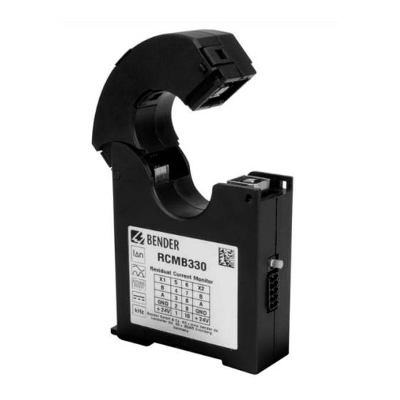
Device view RCMB330 Element Description Unlock cur- Press both elements together simultane- rent trans- ously and flip the RCMB330 open former core For manual test, manual reset, degaussing, "T/R" button offset calibration (use pointed object to press) Combined LED (Refer to "LED" on page 20.) - Page 15 120 Ω 120 Ω DIP switch Jumper Fig. 4.2: Wiring diagram RCMB330 RCMB330 By using the jumper, the internal 120 Ω terminating resistor can be connected. COM465IP By means of the DIP switch, the internal 120 Ω terminating resistor can be connected.
-
Page 16: Installation Instructions For Measuring Current Transformers
Mounting and connection 4.4 Installation instructions for measuring current transformers Do not route any shielded cables through the measuring current transformer! Device damage due to interference pulses! The connecting cable (supply, analogue interface...) must not be routed directly past the current transformer core/primary conductor. CAUTION Protective conductors and live conductors Make sure that all current-carrying cables are routed... -
Page 17: Commissioning
Commissioning 5. Commissioning 5.1 Address setting Every RCMB330 has a factory-set Modbus address. The address is 1XX, where XX = the last two digits of the serial number. Example: Serial number = 12345678 —> Modbus address = 178 If the preset address is to be changed, this can be done •... -
Page 18: Offset Calibration
Commissioning 5.2 Offset calibration The RCMB330 should be calibrated after installation in the system to be monitored. The device can be calibrated by pressing the "T/R" button and via the Modbus interface. Make sure that during the offset calibration the system is switched off and no current flows through the measuring current transformer. -
Page 19: Test And Reset
Commissioning 5.4 Test and reset 5.4.1 Periodic self test The RCMB330 carries out self-diagnosis of the electronics at regular intervals to ensure that the device functions properly. 5.4.2 Manual test/reset The integrated "T/R" button allows a function test to be performed locally at any time. -
Page 20: Led
6. LED The LED indicates the module state by means of colours and lighting/flashing. LED flashing pattern Description Device switched off Device is de-energised, no monitoring, no monitoring function (LED is off). Normal operating state The device is supplied with the specified voltage and ready for operation. It monitors the pri- mary circuit (lights green). -
Page 21: Modbus Registers
Modbus registers 7. Modbus registers This chapter provides a complete description of the Modbus registers for the RCMB330 to allow access to information. The following Modbus function codes are supported: • Holding register for reading out values (Read Holding Register; function code 0x03) •... -
Page 22: Overview Of The Register Areas
Modbus registers 7.1.3 Overview of the register areas Area Start address End address Info 3999 Detailed measured val- 4000 7999 Basic measured values 8000 11999 History 12000 15999 Parameter 16000 19999 Control commands 20000 23999 7.1.4 Representation of values Value Description Value Description... -
Page 23: Alarm Assignments
(\0 = end character) UTF8 B74043160\0 Character is in the LoByte String- 1066 Serial number UTF8 Maximum 96 characters String- Manufacturer Bender GmbH & 1098 (\0 = end character) UTF8 name Co. KG\0 Character is in the LoByte Application 1194 UINT16 firmware Application Version number multiplied by 100. - Page 24 Counter Counts how often complete, success- 1200 UINT32 offset calibration ful offset calibrations were performed. 1202… String- Internet address www.bender.de\ Character is in the LoByte in each case. 1233 UTF8 manufacturer Maximum 32 characters. Installation loca- 1234… String- \0 = NULL character = string end <location>\0...
-
Page 25: Detailed Measured Values
The detailed measured values also include status information and units in addition to the pure measured value. This function is essentially required for the Bender COM- TRAXX® system. Detailed measured values can also be interesting for a direct readout of the Modbus registers, since with these registers the measured values and associated status information can be queried at once and directly one after the other. -
Page 26: Basic Measured Values
Modbus registers Notes Table 7.2 HiByte: Test status; LoByte: Alarm status HiByte: range; LoByte: unit see Table 7.4 7.4 Basic measured values Unit Propert Register Format Description Value Comment Measured value (AC) 8000 Float32 Δn Measured value (DC) 8002 Float32 Δn Measured value (RMS) - Page 27 The error is deleted either by switching the device off/on or by performing a reset. The 6.00 device restarts completely. If the error per- sists, return the device or contact Bender service. No initial No offset calibration has 6.10...
-
Page 28: History
Modbus registers 7.5 History A maximum of 50 events can be stored. The events are sorted chronologically in such a way that the most recent event is number 1 and the oldest event is number 50. The history memory is buffered and is only updated by reading register 12000 so that the sequence does not change during readout (due to a new history event). -
Page 29: Device Parameters And Factory Settings
Modbus registers 7.6 Device parameters and factory settings = response delay = delay on release Value range Factory settings Register Description Unit RCMB330 {Step size} Limit value 30…500 mA 16000 30 mA main alarm {1 mA} Limit value 50 … 100 %... - Page 30 Modbus registers Value range Factory settings Register Description Unit RCMB330 {Step size} 16038 Reserved Alarm assignment 16039 start alarm Alarm assignment 16040 device error 16041 Reserved — Alarm assignment Alarm assignment limit value violation 16042 Δn 1 = inactive prewarning (AC)
- Page 31 Modbus registers Value range Factory settings Register Description Unit RCMB330 {Step size} 16075 16076 Reserved 16077 Last two digits of the 16078 Modbus address 1…247 serial number + 100 1200 2400 4800 16079 Baud rate 9600 19200 19200 38400 57600...
-
Page 32: Control Commands
Modbus registers Notes: Register 16074 "Filter mode" Register entry Description Normal (full bandwidth: 100 kHz) Low pass 60 Hz Low pass 500 Hz Low pass 1 kHz Low pass 2 kHz Low pass 5 kHz Low pass 10 kHz Low pass 20 kHz Low pass 50 kHz Type B Reserved... - Page 33 Modbus registers Comment Factory Register Property Format Description Unit settings Value Flag to allow changing important registers. Allow register write Is automatically deactivated after five sec- 20005 UINT16 access onds. 1 = deny; 2 = allow Makes the LED flash quickly red and green in alternation to detect the device in its Activate device sig- 20006...
-
Page 34: Additional Function Codes
Modbus registers 7.8 Additional function codes 7.8.1 Diagnostic (function code 0x08) Sub-function code Error Sub-function code name Supported Notes number (decimal) counter Return Query Data Restart Communication Return Diagnostic Register Change ASCII Input Delimiter Force Listen Only Mode Reserved 5…9 Clear Counters and Diagnostic Register Return Bus Message Count Return Bus Communication Error Count... -
Page 35: Report Server Id (Function Code 0X11)
Modbus registers 7.8.3 Report Server ID (function code 0x11) Response Notes Byte count Number of bytes from "Server ID" to "Installation location" Server ID Is always 0x01 Run Indicator Status Is always 0xFF Manufacturer name Same information as register 1098 Device name Same information as register 1002 Application D number... -
Page 36: Frequency Responses
Frequency responses 8. Frequency responses 8.1 Low passes LP ∆n 10 x I ∆n 5 x I ∆n 1 x I ∆n 1000 10000 100000 f (Hz) 8.2 Type B+ 1000 (mA) ∆n = 300 mA ∆n = 100 mA ∆n = 30 mA ∆n... -
Page 37: Type B
Frequency responses 8.3 Type B 1000 ∆n (mA) = 30 mA ∆n 1000 f (Hz) 8.4 Fire protection 100 kHz 1000 (mA) ∆n = 300 mA ∆n = 100 mA ∆n = 30 mA ∆n 1000 10000 100000 f (Hz) RCMB330_D00389_00_M_XXEN/12.2020... -
Page 38: Technical Data
Technical data 9. Technical data 9.1 Tabular data Insulation coordination acc. to IEC 60664-1/IEC 60664-3 Definitions Measuring circuit (IC1) .......Primary conductors routed through the current transformer Secondary (IC2) ..............terminal block (24 V, GND, A, B, X1, X2) Rated voltage ..........................300 V Overvoltage category ........................ - Page 39 Technical data Time response Response delay t (prewarning)................50 ms…60 min (1 s)* Response delay t (main alarm)..............50 ms…60 min (50 ms)* Start-up delay t ..............0 s…60 min (freely configurable), (0 s)* Delay on release t ..............0 s…60 min (freely configurable), (1 s)* Operating time t at 1 x I ..........................
-
Page 40: Standards And Certifications
Software............................D0609 Weight ............................≤ 170 g 9.2 Standards and certifications 9.3 Ordering information Electronic modules Supply voltage Variant Type Art. No. DC 24 V (19.2…28.8 V) Modbus RTU RCMB330 B74043160 Accessories Description Art. No. RS-485/USB interface converter B95012045 RCMB330_D00389_00_M_XXEN/12.2020... -
Page 41: Document Revision History
Technical data Suitable system components The use of the listed power supply units is recommended. The use of a surge protection device is mandatory for these power supply units. Max. connected current Description Type Art. No. transformers STEP-PS/1 AC/24 DC/0.5 B94053110 Voltage STEP-PS/1 AC/24 DC/1.75... - Page 42 Technical data RCMB330_D00389_00_M_XXEN/12.2020...
-
Page 43: Index
INDEX Manual test/reset 19 "T/R" button 14 Modbus - Alarm assignments 23 - Basic measured values 26 Address setting 17 - Control commands 32 Application example 11 - Description 23 Area of application 10 - Detailed measured values 25 - Device Identification 35 - Device information 23 Bending cables 16 - Diagnostic 34... - Page 44 INDEX Technical data 38 Terminating resistor 15 Test alarm 19 Training courses 6 Versions 11 Working on electrical installations 9 Workshops 6 RCMB330_D00389_00_M_XXEN/12.2020...
- Page 48 All rights reserved. Reprinting and duplicating only with permission of the publisher. Bender GmbH & Co. KG PO Box 1161 • 35301 Grünberg • Germany Londorfer Str. 65 • 35305 Grünberg • Germany Tel.: +49 6401 807-0 • Fax: +49 6401 807-259 email: info@bender.de •...
Need help?
Do you have a question about the RCMB330 and is the answer not in the manual?
Questions and answers