
Related Manuals for Bender RCMB101


Summary of Contents for Bender RCMB101
- Page 1 User Manual RCMB101 CCID-20 AC/DC Ground Fault Current Module for Electric Vehicle Charging Stations Software version D359 V2 Power in electrical safety NAE1045320/11.2011...
- Page 2 Bender Inc. USA: 700 Fox Chase Coatesville, PA 19320 Toll Free: 1-800-356-4266 Phone: 610-383-9200 Fax: 610-383-7100 Canada: 5 Edvac Drive, Unit 14 Brampton, ON L6S 5P3 Toll Free: 800-243-2438 Phone: 905-799-0840 Fax: 905-799-3051 © Bender Inc. E-mail: info@bender.org Web: http://www.bender.org All rights reserved.
-
Page 3: Table Of Contents
Switching output X12 ......................8 Control input X10 ........................9 2.6.1 Reset function ........................... 9 2.6.2 Reset and subsequent calibration of the RCMB101 ..........10 2.6.3 Measuring sequence without charging electronics reset ........12 2.6.4 Verifying proper functionality of and testing X12 ............ 13 Starting sequence ......................... - Page 4 Table of Contents 4. Technical data ....................... 22 Data in tabular form ......................22 Ordering information ......................23 Approvals / Certifications ....................23 Dimension diagrams ......................24 NAE1045320/09.2011...
-
Page 5: Safety Instructions
Only use manufacturer’s and manufacturer recommended accessories with this equipment. Failure to do so may damage the equipment beyond repair. The RCMB101 is designed in compliance with the requirements described in UL 2231-2, "Standard for personnel protection systems for electric vehicle (EV) supply circuits: Particular requirements for protection devices for use in charging systems."... - Page 6 Safety Instructions NAE1045320 / 11.2011...
-
Page 7: Function
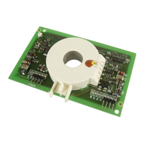
2.2 Description The RCMB101 is a ground fault current module (CCID20) for monitoring AC/DC ground faults in elec- tric vehicle charging stations. The CCID20 shall be mounted into the charging station as an open- type circuit board. The electrical connection is made with circuit board plug connectors. -
Page 8: Cyclical Self Test
Function 2.3.2 Cyclical self test Before each charging cycle, a reset with subsequent calibration has to be activated by the charging control electronics via the input X10. This requirement can only be met when sufficient supply volt- age +U /- U is available. -
Page 9: Control Input X10
Enabling for measuring operation Start of residual current measurement A RESET of the RCMB101 can be carried out at any time via the control input X10. NOTE: The ground fault current measurement is interrupted during this time. For activating the RESET function, a LOW level is to be applied across the control input X10 for at least T1 >... -
Page 10: Reset And Subsequent Calibration Of The Rcmb101
Function 2.6.2 Reset and subsequent calibration of the RCMB101 ~ ~ ~ ~ NAE1045320 / 11.2011... - Page 11 Once the calibration procedure is completed (X12 to LOW), calibration can be repeated as frequently as desired by applying a HIGH level at X10 for T2 = 50...100 μs. The RCMB101 starts the ground fault current measurement when a HIGH level is applied at X10 for at least T5 = 5 ms.
-
Page 12: Measuring Sequence Without Charging Electronics Reset
Function 2.6.3 Measuring sequence without charging electronics reset If a LOW level is applied across the control input X10 of the residual current monitoring module for T < 530 ms, no RESET will be carried out. The outputs X1 and X12 will remain unaffected. The residual current measurement will stay active. -
Page 13: Verifying Proper Functionality Of And Testing X12
Function 2.6.4 Verifying proper functionality of and testing X12 t = 0 time t[sec] 1.8s 2.3s 75μs Control • 530ms input X10 Switching output X12 600ms..850ms 11ms Analog output X1 for reference only Start of self test Apply test current 10mA/400Hz Apply test current 22mA DC... -
Page 14: Starting Sequence
Function 2.7 Starting sequence The RCMB101 is supplied by an external power supply. Supply voltage fluctuations can influence measurements. To exclude this effect (calibration is considerably affected!), the following starting se- quence is applied: The starting sequence of the module begins when a supply voltage of U 5 V is applied. - Page 15 Function Starting sequence Us+ >= 5 V X12 = HIGH US+ >= 11 V Offset measurement US+ >= 11 V 0,5 s X12 = LOW 0,1 s Start I-measurement Switch on test current through test winding 2,0 s Stop I-measurement Switch off test current 0,1 s through test winding...
-
Page 16: Values Outside The Permissible Measuring Range
If the ground fault current exceeds the measuring range ( 20mA), the RCMB101 will switch the Open-Collector output to HIGH once the measuring time T1 has elapsed. In comparison to the switching output X12, the voltage at the analog output X1 increases with a de- lay of U = 4.85 V within the time T2. -
Page 17: Measuring Range And Switching Times
2.9.2 Switching times without a contactor The time the RCMB101 needs for signaling a disconnection with switching output X12 is at least 10ms below the disconnection time required by the UL 2231 standard. Please consider that the actual interruting device/contactor chosen by the... -
Page 18: Fault Detection And Resulting Reactions
Function 2.10 Fault detection and resulting reactions Type of fault Detection Reaction Frequency measurement Wire break in the X1 = 5.0 V via CT test input current transformer X12 = HIGH at the controller Short-circuit in the Frequency measurement X1 = 5.0 V current transformer wind- via CT test input X12 = HIGH... -
Page 19: Installation And Connection
3. Installation and connection 3.1 Installation Refer to dimension diagrams on page 23. 3.2 Terminal assignment X11 X10 X9 X3 X2 X1 Plug designation Description Analog voltage output : Voltage supply -12 V / -15 V via current limiting or 100 mA fuse recommended GND: ground not connected GND: ground... -
Page 20: Conductor Routing Through Current Transformer
Switching output X12 and analog output X1 are monitored by charger to verify that X1 and X12 show consistent information and that the behavior after a test (initiated with X10) is correct. RCMB101 to Load cable Mains... - Page 21 Installation and connection NAE1045320 / 11.2011...
-
Page 22: Technical Data
Technical data 4. Technical data 4.1 Data in tabular form Voltage supply + (X11) ..................+12 V (± 1 V) – (X2) ..................–12 V (± 1 V) ................... 100 mV Ripple at U Power consumption .................. 1 W Measuring circuit Operating characteristic acc. -
Page 23: Ordering Information
4.2 Ordering information Measuring Type Frequency range Art. No. range RCMB101 0…20 mA 0…500 Hz B 9404 2098 4.3 Approvals / Certifications File # E193871, UL 2231-2, "Standard for personnel protection systems for electric vehicle (EV) supply circuits: Particular requirements for pro- tection devices for use in charging systems"... -
Page 24: Dimension Diagrams
Technical data 4.4 Dimension diagrams Dimensions are given in mm NAE1045320 / 11.2011... - Page 25 Technical data NAE1045320 / 11.2011...
- Page 26 Technical data NAE1045320 / 11.2011...
- Page 28 Bender Inc. USA: 700 Fox Chase Coatesville, PA 19320 Toll Free: 800-356-4266 Phone: 610-383-9200 Fax: 610-383-7100 Canada: 5 Edvac Drive, Unit 14 Brampton, ON L6S 5P3 Toll Free: 800-243-2438 Phone: 905-799-0840 Fax: 905-799-3051 E-mail: info@bender.org Web: http://www.bender.org...
Need help?
Do you have a question about the RCMB101 and is the answer not in the manual?
Questions and answers