
Related Manuals for Bender RFID110-L1


Summary of Contents for Bender RFID110-L1
- Page 1 Manual RFID110-L1 For use in combination with charge controllers used in electric vehicle charging stations, wall boxes and street light charging points RFID110-L1_D00283_02_M_XXEN/04.2018...
- Page 2 Bender GmbH & Co. KG P.O. Box 1161 • 35301 Grünberg • Germany Londorfer Strasse 65 • 35305 Grünberg • Germany Tel.: +49 6401 807-0 • Fax: +49 6401 807-259 E-Mail: info@bender.de • www.bender.de © Bender GmbH & Co. KG All rights reserved.
-
Page 3: Table Of Contents
Table of Contents 1. Important information ..................5 How to use this manual ................. 5 Technical support: service and support ........... 5 Delivery conditions ..................6 Inspection, transport and storage .............. 6 Disposal ....................... 6 Intended use ...................... 6 2. RFID module ..................... 8 Dimensions for mounting ................ - Page 4 Table of Contents RFID110-L1_D00283_02_M_XXEN/04.2018...
-
Page 5: Important Information
This symbol denotes information intended to assist the user in making optimum use of the product. 1.2 Technical support: service and support Technical support by phone or e-mail for all Bender products. Questions concerning specific customer applications Commissioning ... -
Page 6: Delivery Conditions
Important information 1.3 Delivery conditions Bender sale and delivery conditions apply. These can be obtained from Bend- er in printed or electronic format. 1.4 Inspection, transport and storage Inspect the dispatch and equipment packaging for damage, and compare the contents of the package with the delivery documents. In the event of damage in transit, please contact Bender immediately. - Page 7 Charging is initiated by holding a valid RFID card, which is registered to a backend system, close to the reader on the RFID module. Charging starts when the contactor in the charging system is switched on to provide power flow. In offline operation, the charge controller can optionally allow charging without authorization or it can authorize users based on RFID and a local white list of authorized RFID cards.
-
Page 8: Rfid Module
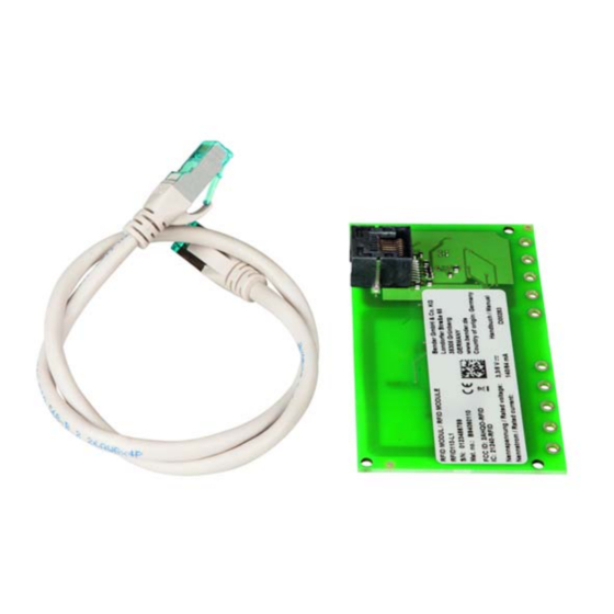
RFID module 2. RFID module The RFID module, shown below, contains an antenna, antenna illumination and status LEDs. 102.89 Free 5 white LEDs Status LEDs (illuminated during Reserved authorisation process) Charging Note: Tolerance acc. to ISO 2768 - m All dimensions in mm It is a separate PCB that should ideally be placed under a semi-transparent part of the charging system housing. -
Page 9: Dimensions For Mounting
RFID module The RFID frequency is 13.56 MHz. Bender uses the PN532 Near Field Com- munication (NFC) controller for contactless communication, which supports virtually all RFID/NFC communication means on this frequency. Currently only passive tags with a UID are read. Further functionality is possible upon request. -
Page 10: Rfid Status Leds
RFID module 2.2 RFID status LEDs As well as the RFID antenna, the RFID module contains several LEDs: three sta- tus LEDs, one each in green (Free), yellow (Reserved) and blue (Charging), and 5 white LEDs set in a circular arrangement. The status of the LEDs changes when charging is initiated by holding a valid RFID card close to the reader on the RFID module. -
Page 11: Operation
Charging can be terminated when the RFID card is again held in front of the charging system. 2.4 Integration The RFID module is integrated solely in conjunction with Bender charge con- trollers under professional installation. In most cases these charge controllers implement the functionality of an electric vehicle charging system in which the RFID module is used to authorize charging transactions. -
Page 12: Host Labelling Requirements
RFID module 2.4.2 Host labelling requirements: The RFID module is provided with a special label which contains all necessary information. The use of the RFID module in combination with a special host may, depending on the circumstances, require additional documentation if: The module's Federal Communications Commission (FCC) ID is not ... -
Page 13: Canada Rss-Gen § 8.4
RFID module 2.5.2 Canada RSS-GEN § 8.4 This device complies with Industry Canada's licence-exempt RSSs. Operation is subject to the following two conditions: 1. This device may not cause interference 2. This device must accept any interference, including interference that may cause undesired operation of the device. -
Page 14: Technical Data
Technical data 3. Technical data 3.1 Tabular data Insulation coordination acc. to IEC 60664-1/IEC 60664-3 Rated voltage ................................ 12.5 V Overvoltage category..............................III Pollution degree ................................3 Rated impulse withstand voltage........................... 800 V Rated insulation voltage............................12.5 V Altitude..............................≤ 2000 m AMSL Nominal voltage/nominal current Nominal voltage..............................DC 3.3/5 V Nominal voltage tolerance ............................ -
Page 15: Standards, Approvals, Certifications
Technical data 3.2 Standards, approvals, certifications The RFID110-L1 module has been developed in compliance with: ISO 14443A/MIFARE EN 50364: 2010 EN 60950-1: 2006 + A11: 2009 + A1: 2010 + A12: 2011 + AC: 2011 ... -
Page 16: Declaration Of Conformity
Technical data 3.4 Declaration of conformity Bender GmbH & Co. KG Postfach 1161 • 35301 Grünberg/Germany Londorfer Straße 65 • 35305 Grünberg/Germany Phone: +49 6401 807-0 • Fax: +49 6401 807-259 E-Mail: info@bender.de • www.bender.de EG - K o n f o r m i t ä t s e r k l ä r u n g... - Page 17 Anlage - Typenliste der EG-Konformitätserklärung RFID11x Annex - Typelist of EC-declaration RFID11x Produktgruppe Art.-Nr. Gerätebezeichnung Product group Art.-no. Device type CC61x B94060110 RFID110-L1 RFID B94060114 RFID114 ohne LEDs WEEE-Reg.-Nr. DE 43 124 402 Ausgabe/revision: 1 Seite/page 2 von 2 RFID110-L1_D00283_02_M_XXEN/04.2018...
- Page 18 Technical data RFID110-L1_D00283_02_M_XXEN/04.2018...
- Page 20 Bender GmbH & Co. KG P.O. Box 1161 • 35301 Grünberg • Germany Londorfer Strasse 65 • 35305 Grünberg • Germany Tel.: +49 6401 807-0 • Fax: +49 6401 807-259 E-Mail: info@bender.de • www.bender.de Group Photos: Bender archives...
Need help?
Do you have a question about the RFID110-L1 and is the answer not in the manual?
Questions and answers