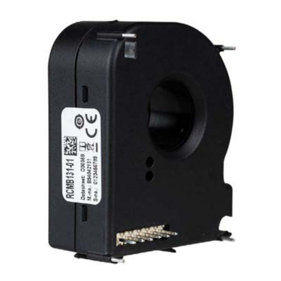
Summary of Contents for Bender RCMB131-01
- Page 1 Manual EN RCMB131-01 AC/DC sensitive residual current monitoring module for measuring AC and DC currents up to ±100 mA RCMB131-01_D00358_02_XXEN / 05.2024...
-
Page 2: General Safety Instructions
• Supply voltage DC 12…24 V Functional description The RCMB131-01 is used to measure residual currents and output the values via an interface. The residual current monitoring module measures both AC and DC currents. The RMS value is cal- culated from the DC component included in the residual current and the AC component below 2000 Hz. -
Page 3: Dimension Diagram
RCMB131-01 Via the RS-485 interface: • a signal proportional to the RMS value is transmitted (measured value update every 180 ms) • alarm messages are signalled • response values are configured • a functional test can be started The existing switching outputs S1 and S2 switch to alarm state when the set response value is exceeded or a malfunction occurs. -
Page 4: Pin Assignment
RCMB131-01 Pin assignment Name Description Supply voltage (DC 12…24 V) Ground Switching output 2 (RMS) RS-485-B 1 2 3 4 5 6 Switching output 1 (DC) RS-485-A The switching outputs S1 and S2 are for monitoring purposes only and may only be used from a set response differential current set differential response current I ≥... - Page 5 RCMB131-01 Timing diagram “Functional test” As soon as it is detected that register 4000 has the value 0, time measurement starts with t = 0. M1…3 in the timing diagram are the points in time at which a higher-level control can and should check during the functional test that the switching outputs S1…2 actually switch independently...
-
Page 6: Modbus Register Overview
RCMB131-01 Modbus register overview Supported function codes: 0x03 Read Holding Registers 0x04 Read Input Registers 0x06 Write Single Register 0x10 Write Multiple Registers Properties of the registers: Read Only Write Only Read and Write “Broadcast” (address “0”): Execute action, do not send a response. Broadcast only works with “write”... - Page 7 RCMB131-01 Status word 1 Status byte Meaning Value 0 = error, deactivated Bit 0 Status ERR_OUT 1 = no error, activated Bit 1 Status S1 0 = off, deactivated, triggered 1= on, activated, not triggered Bit 2 Status S2 Bit 3...
- Page 8 RCMB131-01 Control (test, reset, find module) Register Property Description Format Comment/Unit Range 0 = start functional test without offset measurement 1 = start functional test with offset measurement Test = approx. 2 s 4000 Test & reset UINT16 (see timing diagram)
- Page 9 RCMB131-01 Register 60000 can only be written together with the correct register content from 60001…60003. The three registers are used as an extension of the Modbus address and only the slave with matching Modbus address and serial number reacts. Write: address a specific module When writing together with register 60000 the factory-set serial number of the module from register 2009 is entered.
- Page 10 RCMB131-01 2. Assign new bus address when the serial number is known Prerequisite: The serial numbers of the modules are known. Each module must have its own Modbus address via which it can be addressed. If the addresses were not assigned during the setup phase and therefore several modules have the same address (factory setting: 100), the known serial number can be used as an extension of the Modbus ad- dressing.
-
Page 11: Technical Data
RCMB131-01 Technical data Insulation coordination according to IEC 60664-1 Disturbances Primary circuit .......monitored primary conductors Load current I ...............32 A Secondary circuit .....Connections Vcc, GND, A, B, S1, S2 Response value assignment All following specifications apply to the insulation between the (DC) ..................S1... -
Page 12: Standards, Approvals, Certifications
Alle Rechte vorbehalten. 35305 Grünberg Nachdruck und Vervielfältigung nur mit Germany Genehmigung des Herausgebers. © Bender GmbH & Co. KG, Germany Subject to change! The specified Tel.: +49 6401 807-0 All rights reserved. standards take into account the edition info@bender.de...


Need help?
Do you have a question about the RCMB131-01 and is the answer not in the manual?
Questions and answers