
Related Manuals for Bender RCMB103


Summary of Contents for Bender RCMB103
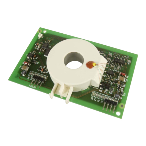
- Page 1 Operating Manual RCMB103 AC/DC sensitive residual current monitoring module for installation into electric vehicle charging stations Software version D396 V1 RCMB103_D00044_00_M_XXEN/08.2013...
- Page 2 Bender GmbH & Co. KG Londorfer Str. 65 • 35305 Grünberg • Germany Postfach 1161 • 35301 Grünberg • Germany © Bender GmbH & Co. KG Tel.: +49 6401 807-0 All rights reserved. Fax: +49 6401 807-259 Reprinting only with permission E-mail: info@bender-de.com...
-
Page 3: Table Of Contents
2.6.2 Reset function ........................11 2.6.3 Impulse duration for activating a reset ................. 11 2.6.4 Self test: Reset and subsequent calibration of the RCMB103 ....... 12 2.6.5 Functional test switching output X12 ................14 Values outside the permissible measuring range ............. 15 Measuring range and switching times ................ - Page 4 Table of Contents 3. Installation and connection ................17 Installation ..........................17 Connection assignment ...................... 17 Example applications ......................18 3.3.1 The circuit-breaker is controlled by the charging control electronics and the switching output X12 ......................18 3.3.2 The circuit-breaker is controlled by the charging control electronics ....18 4.
-
Page 5: Safety Instructions
Observe the associated safety instructions! 1.3 Intended use The AC/DC sensitive residual current monitoring module RCMB103 is used for monitoring residual currents in charging stations for electric vehicles where direct and/or alternating residual currents are likely to occur the value of which is constantly greater than zero. This also applies to the detection of leakage currents. -
Page 6: Warranty And Liability
1.4 Warranty and liability Bender devices are designed and built in accordance with the state of the art and accepted rules in respect of technical safety. However, the use of such devices may introduce risks to the life and limb of the user or third parties and/or result in damage to Bender devices or other property. -
Page 7: Function
The control input (X10) will also be queried. Depending on the sequence of the HIGH/LOW levels applied, the RCMB103 can be reset with or without a self test, calibration and activation of the test winding (test current supply). -
Page 8: Starting Sequence
2.3 Starting sequence Once the residual current monitoring module is connected to the power supply, the automatic starting sequence begins. The residual current monitoring module RCMB103 is supplied by an external power supply. Note: Users must ensure that the supply voltages +U... - Page 9 Function Starting sequence +U s ≥ 5 V X12 = HIGH +U s ≥ 11 V Calibration (offset measurement) +U s ≥ 11 V 0.5 s X12 = LOW 0.1 s Switch on the test current in the test winding 2.0 s Test current measurement...
-
Page 10: Analogue Voltage Output X1
Function 2.4 Analogue voltage output X1 A signal in proportion to the DC component is available at the analogue voltage output X1. If the residual current monitoring module detects values outside the measuring range, the analogue output X1 will be set to 4.85 V. As soon as the residual current drops below 3.5 mA, the output X1 will still remain at 4.85 V for approx. -
Page 11: Reset Function
Function 2.6.2 Reset function A reset of the residual current monitoring module can be carried out at any time via the control input X10. For activating the reset function, a LOW level is to be applied across the control input X10 for at least T1 >... -
Page 12: Self Test: Reset And Subsequent Calibration Of The Rcmb103
Function 2.6.4 Self test: Reset and subsequent calibration of the RCMB103 ~ ~ ~ ~ RCMB103_D00044_00_M_XXEN/08.2013... - Page 13 Function The signalling sequence at the control input X10, illustrated in the preceding diagram, results in a self test as a reset and subsequent calibration. The self test includes a test of the supply voltage before and after zero point measurement. If the supply voltage is outside the tolerance, calibration will be repeated.
-
Page 14: Functional Test Switching Output X12
Function 2.6.5 Functional test switching output X12 t = 0 time t[s] 1.8 s 2.3 s 75 μs Control ≥ 530 ms input X10 Switching output X12 11 ms Analog output X1 for reference only ≤ 200 ms Start of self test Apply test current 3.8 mA DC Apply test current... -
Page 15: Values Outside The Permissible Measuring Range
Function 2.7 Values outside the permissible measuring range T2 = 1.2 s 6 mA HIGH Switching output X12 4.85 V Voltage output X1 0.15 V Connecting residual current ≥ 6 mA Δn T1: Switch-off time (X12) depending upon the residual current Fig. -
Page 16: Measuring Range And Switching Times
Function 2.8 Measuring range and switching times Measuring range The measuring range of the residual current is 0…6 mA DC according to IEC62752, tab. 2b. Switching time residual current monitoring module (without switching device) The maximum switching times of the output X12 is dependent on the residual current. Residual current Δn Switching time T1 of the output X12... -
Page 17: Installation And Connection
3. Installation and connection 3.1 Installation Refer to dimension diagrams page 21. 3.2 Connection assignment X11 X10 X9 X3 X2 X1 Plug designation Description Analogue voltage output : Voltage supply -12 V via current limiting or 100 mA fuse recommended GND: ground not connected GND: ground... -
Page 18: Example Applications
The switching output X12 and the analogue output X1 are monitored by the charging system to ensure that the outputs always provide consistent information. Furthermore, it is checked that the behaviour after a test triggered by control input X10 is correct. RCMB103 Mains to Load cable... -
Page 19: Technical Data
4. Technical data 4. 1 Data in tabular form Voltage supply (X11) ..............................12 V (± 1 V) (X2)................................-12 V (± 1 V) Ripple U ................................≤100 mV Power consumption ..............................≤ 1 W Measuring circuit Operating characteristic acc. to ......................IEC 62752, tab. 2b Frequency range .............................. -
Page 20: Ordering Information
................................. 3M: 960104-6202-AR Modular dimensions ............................2.54 mm Other Operating mode ..........................continuous operation Position of normal use ..............................any Software version..............................D396 V1 Weight ..................................≤ 65 g 4. 2 Ordering information Measuring Type Art. No. range RCMB103 0…6 mA DC B 9404 2105 RCMB103_D00044_00_M_XXEN/08.2013... -
Page 21: Dimension Diagrams
Technical data 4. 3 Dimension diagrams Dimensions are given in mm RCMB103_D00044_00_M_XXEN/08.2013... - Page 22 Technical data RCMB103_D00044_00_M_XXEN/08.2013...
- Page 24 D0004400MXXEN Bender GmbH & Co. KG Londorfer Str. 65 • 35305 Grünberg • Germany Postfach 1161 • 35301 Grünberg • Germany Tel.: +49 6401 807-0 Fax: +49 6401 807-259 E-Mail: info@bender-de.com Web: http://www.bender-de.com...
Need help?
Do you have a question about the RCMB103 and is the answer not in the manual?
Questions and answers