
Related Manuals for Bender RCMA126P1-S


Summary of Contents for Bender RCMA126P1-S
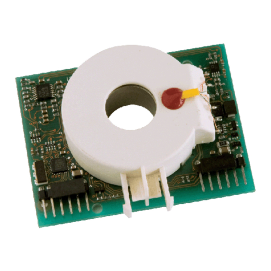
- Page 1 Operating Manual RCMA126P1-S AC/DC sensitive residual current monitoring module for installation into photovoltaic converters Software version 9 Power in electrical safety TGH1423en/04.2010...
- Page 2 Dipl.-Ing. W. Bender GmbH & Co. KG Londorfer Str. 65 • 35305 Grünberg • Germany Postfach 1161 • 35301 Grünberg • Germany Tel.: +49 6401 807-0 Fax: +49 6401 807-259 © Dipl.-Ing. W. Bender GmbH & Co. KG E-mail: info@bender-de.com Web: http://www.bender-de.com...
-
Page 3: Table Of Contents
Table of Contents 1. Effective use of this manual .................. 5 Notes for the user ........................5 2. Safety information ....................7 General safety information ....................7 Work activities on electrical installations ................ 7 3. Function ........................9 Product description ......................... 9 Function ............................ - Page 4 Table of Contents 5.5.2 Measuring times ........................18 6. Technical data ....................... 19 Data in tabular form ......................19 Ordering information ......................20 Dimension diagrams ......................21 TGH1423en/04.2010...
-
Page 5: Effective Use Of This Manual
1. Effective use of this manual 1.1 Notes for the user This manual is intended for electrically skilled persons in electrical engineering and electronics! In order to make it easier for you to find specific text passages or references in this manual and for reasons of comprehensibility, important information is emphasised by symbols. - Page 6 Effective use of this manual TGH1423en/04.2010...
-
Page 7: Safety Information
2.1 General safety information In addition to this data sheet, the documentation of the device includes a sheet entitled "Im- portant safety instructions for Bender products“. 2.2 Work activities on electrical installations All work activities necessary for installation, commissioning or work activities during operation of electrical devices or systems are to be carried out by adequately skilled personnel. - Page 8 Safety information TGH1423en/04.2010...
-
Page 9: Function
3. Function 3.1 Product description The AC/DC sensitive residual current monitoring module RCMA126P1-S is suitable for fault current monitoring in transformerless photovoltaic inverters where direct and/or alternating fault currents are likely to occur the value of which is constantly greater than zero. - Page 10 Function TGH1423en/04.2010...
-
Page 11: Installation, Connection
4. Installation, connection 4.1 Connection assignment 8 9 10 Plug designation Description PWM (measured value output) CS (ChipSelect interface) SCK (CLOCK interface) MISO (data output interface) MOSI (data input interface) U4 (voltage supply +3.3 V) U2 (voltage supply +5 V) AGND (ground) U3 (voltage supply -5 V) (voltage supply +15 V) - Page 12 Installation, connection TGH1423en/04.2010...
-
Page 13: Operation And Setting
5. Operation and setting 5.1 PWM measured value output X1 The measured residual current is available at the measurement output X1 as a PWM signal in proportion to the residual current. Values outside the permissible measuring range are available for approximately 1s after disconnection. The PWM frequency is 8 kHz. Sensitivity of the device: Measuring range 30 mA: M = 30 mA / 97 % = 0.3093 mA/% pulse width 0...30 mA equates to 0...97 %, where measured values <... -
Page 14: Spi Timing
Operation and setting 5.2.1 SPI timing 5.2.1.1 Timing for the receipt of one byte from the master MOSI (sampling) MISO Bit6 Bit5 Bit4 Bit3 Bit2 Bit1 > 20ns SPI signals: SCK: Clock, generated by the master MOSI: Data is sampled by slave MISO: Data output from slave Slave-Select signal from master... -
Page 15: Messages
The response to this command will be written into "Answer" register. In this case "Answer" from RCMA126P1-S means that the received value will be written into the SPI send register. The master can get this answer byte by sending a dummy command (0x00h) to which the RCMA126P1-S does not initiate an action. -
Page 16: Hardware Version Query
1 %. Meaning of the bits: Bit 0: 1 = RCMA126P1-S active, the output measuring signal is valid Bit 1: specifies the currently set measuring range Bit 2: is 1 during the initialisation phase of the software and during the cyclic self test of the RCMA126P1-S (approx. -
Page 17: Function Control
Operation and setting 5.2.2.6 Function control Converter Command Send 0x82h >= 0x00h The value returned will be incremented each RCMA126 Answer time a command is requested and will be reset to 0x00h when 0xffh is exceeded. For function control, the residual current monitoring module returns a value which is incre- mented whenever a command is requested. -
Page 18: Other Software Features
Operation and setting 5.4 Other software features START Condition: U4 > 3 V Status: Device inactive PWM output: 1 % max. 100ms Functional test Condition: U1 >= 13.9V Offset measurement max. 2s Status: Device inactive Condition: U1>13.5V Residual current measur. Status: Device active PWM output: >=3% The microcontroller only becomes active if the minimum supply voltage U4 >... -
Page 19: Technical Data
6. Technical data 6.1 Data in tabular form Voltage supply U1................................. +15 V (±5 %) U2..............................+5 V (+12 % / -5 %) U3............................... -5 V (+12 % / -5 %) U4..............................+3.3 V (+10 % / -5 %) Ripple max................................. 60 mV Power consumption ............................. -
Page 20: Ordering Information
Modular dimensions ............................2.54 mm Other Operating mode ..........................continuous operation Position of normal use ..............................any ≤ Weight..................................55 g 6.2 Ordering information Measuring Type Frequency range Art. No. range RCMA126P1-S 0…30 / 100 mA 0…500 Hz B 9404 2085 TGH1423en/04.2010... -
Page 21: Dimension Diagrams
Technical data 6.3 Dimension diagrams Dimensions are given in mm Bender p.c.b. RCMA126P1-S of 1.5 mm thickness Bender p.c.b. on base plate Base plate Features: of 1.7 mm thickness, tolerance: +0.1 mm / -0 mm 17,145 17,145 2,54 2,54 Ø 1 Ø... - Page 22 Technical data TGH1423en/04.2010...
- Page 24 Dipl.-Ing. W. Bender GmbH & Co. KG Londorfer Str. 65 • 35305 Grünberg • Germany Postfach 1161 • 35301 Grünberg • Germany Tel.: +49 6401 807-0 Fax: +49 6401 807-259 E-Mail: info@bender-de.com Web: http://www.bender-de.com...
Need help?
Do you have a question about the RCMA126P1-S and is the answer not in the manual?
Questions and answers