Knick Stratos Pro A2 MSPH Series User Manual
Ph measurement with memosens sensors
Hide thumbs
Also See for Stratos Pro A2 MSPH Series:
- Quick start manual (72 pages) ,
- Instruction manual (112 pages) ,
- Quick start manual (72 pages)
Table of Contents
Advertisement
Quick Links
User Manual
Betriebsanleitung
Stratos®Pro
Aktuelle Produktinformation: www.knick.de
Latest Product Information: www.knick.de
Stratos Pro A2.. MSPH
pH Measurement
Stratos Pro A2... pH
with Memosens Sensors
English
deutsch
Betriebsanleitung
Aktuelle Produktinformation:
www.knick.de
The Art of Measuring.
A2... PH
MEMO
SENS
II 1G Ex ia IIC T3/T4/T6
14163 Berlin
14163 Berlin
SE 706X/1-NMSN
SE 706X/2-NMS
14163 Berlin
BVS 10 ATEX E0
BVS 10 ATEX E089 X
II 1G Ex ia IIC T
SE 706X/1-NM
II 1G Ex ia IIC T3/T4/T6
BVS 10 ATEX E
14163 Berlin
II 1G Ex ia IIC
SE 706X/2-NMSN
14163 Berlin
SE 706X/2-NM
BVS 10 ATEX E089 X
II 1G Ex ia IIC T3/T4/T6
BVS 10 ATEX E
II 1G Ex ia IIC
Advertisement
Table of Contents

Related Manuals for Knick Stratos Pro A2 MSPH Series


Summary of Contents for Knick Stratos Pro A2 MSPH Series
- Page 1 Stratos Pro A2.. MSPH pH Measurement User Manual Betriebsanleitung Stratos Pro A2... pH Stratos®Pro with Memosens Sensors English deutsch A2... PH Betriebsanleitung x ia IIC T3/T4/T6 ATEX E 089 X MEMO SENS Aktuelle Produktinformation: Aktuelle Produktinformation: www.knick.de Latest Product Information: www.knick.de www.knick.de...
- Page 2 About This Manual Return of products Please contact our Service Team before returning a defective device. Ship the cleaned device to the address you have been given. If the device has been in contact with process fluids, it must be de- contaminated/disinfected before shipment.
-
Page 3: Documents Supplied
Installation and first steps: • Operation • Menu structure • Calibration • Error messages and recommended actions Specific Test Report Electronic Documentation Manuals + Software Ex Devices: Control Drawings EU Declarations of Conformity Up-to date documentation available on our website: www.knick.de... -
Page 4: Table Of Contents
Contents Documents Supplied ..............3 Introduction ..................7 Intended Use ....................7 Safety Information ...............10 Overview of Stratos Pro A2... MSPH..........11 Assembly ..................12 Package Contents ..................12 Mounting Plan, Dimensions ..............13 Pipe Mounting, Protective Hood ............14 Panel Mounting .....................15 Installation ..................16 Installation Instructions ................16 Rating Plates / Terminal Assignments...........16 Wiring of Stratos Pro A2... - Page 5 Contents Configuration ................32 Menu Structure of Configuration ............32 Manual switchover of parameter sets A/B ..........34 Configuration (Template for Copy) ............40 Sensor .......................42 Sensor Verification (TAG, GROUP) ............52 Current Output 1 ..................54 Current Output 2 ..................62 Temperature Compensation ..............64 CONTROL Input .....................68 Alarm Settings ....................70 Time and Date ....................74 Measuring Points (TAG/GROUP) ............74...
- Page 6 Contents A2...X: Supply Units and Connection ........105 Product Line and Accessories ..........106 Specifications ................107 Buffer Tables ................112 -U1- Specifiable Buffer Set ..............122 Error Handling ................125 Error Messages ................126 Sensoface ..................129 FDA 21 CFR Part 11 ..............132 Electronic Signature – Passcodes ............132 Audit Trail .....................
-
Page 7: Introduction
Introduction Intended Use Stratos Pro A2... MSPH is used for pH/mV, ORP and temperature measurement using Memosens sensors in industry, environment, food processing and sewage treatment. Enclosure and mounting possibilities • The sturdy molded enclosure is rated IP 67/NEMA 4X for outdoor use. - Page 8 Introduction Display Plain-text messages in a large, backlit LC display allow intuitive operation. You can specify which values are to be displayed in standard measuring mode (“Main Display”, see page 25). Color-coded user interface The colored display backlighting signals different operating states (e.g.
- Page 9 Introduction Control inputs I input Current Input + The analog (0) 4 ... 20 mA current input can be used for external temperature compen- Input – input sation (TAN required). See page 66. HOLD HOLD + HOLD (floating digital control input) HOLD –...
-
Page 10: Safety Information
Safety Information Be sure to read and observe the following safety instructions! The device has been manufactured using state of the art technology and it complies with applicable safety regulations. When operating the device, certain conditions may nevertheless lead to danger for the operator or damage to the device. When using the device in a hazardous location, observe the specifications of the Control Drawing. -
Page 11: Overview Of Stratos Pro A2
Overview Overview of Stratos Pro A2... MSPH + Output 1, 2 / HART +3 V Output 1 RS 485 RS 485 A – Output 1 / HART RS 485 B GND/Shield Output 2 – Output 2 Current Input + Input – input HOLD HOLD +... -
Page 12: Assembly
Assembly Package Contents Check the shipment for transport damage and completeness! The package should contain: • Front unit, rear unit, bag containing small parts • Specific test report • Documentation (cf p. 3) Fig.: Assembling the enclosure 1) Jumper (3 x) 6) Sealing insert (1 x) 2) Washer (1 x), for conduit 7) Rubber reducer (1 x) -
Page 13: Mounting Plan, Dimensions
Assembly Mounting Plan, Dimensions 1) Cable gland (3 x) 2) Knockouts for cable gland or ½” conduit, 21.5 mm dia. (2 knockouts) Conduit couplings not included! 3) Knockout for pipe mounting (4 x) 4) Knockout for wall mounting (2 x) Fig.: Mounting plan (All dimensions in mm!) -
Page 14: Pipe Mounting, Protective Hood
Assembly Pipe Mounting, Protective Hood ø40...ø60 1) Hose clamp with worm gear drive to DIN 3017 (2 x) 2) Pipe-mount plate (1 x) 3) For vertical or horizontal posts or pipes 4) Self-tapping screw (4 x) Fig.: Pipe-mount kit, accessory ZU 0274 (All dimensions in mm!) Fig.: Protective hood for wall and pipe mounting, accessory ZU 0737 (All dimensions in mm!) -
Page 15: Panel Mounting
Assembly Panel Mounting < 30 1) Circumferential sealing (1 x) 2) Screws (4 x) 3) Position of control panel 4) Span piece (4 x) 5) Threaded sleeve (4 x) Cutout 138 x 138 mm (DIN 43700) 1...22 Fig.: Panel-mount kit, accessory ZU 0738 (All dimensions in mm!) -
Page 16: Installation
Installation Installation Instructions • Installation of the device must be carried out by trained experts in accordance with this user manual and as per applicable local and national codes. • Be sure to observe the technical specifications and input ratings during installation! •... -
Page 17: Wiring Of Stratos Pro A2
Installation Wiring of Stratos Pro A2... MSPH Areas for placing the screwdriver to pull out the terminals Terminal row 1 Terminal row 2 1 (BN) hold 2 (GN) RS 485 A hold 3 (YE) RS 485 B n.c. 4 (WH) GND/shield contr + input... -
Page 18: Connecting A Memosens Sensor
Connecting a Memosens Sensor Area for placing the screwdriver to pull out the terminals HART Memosens connection: Wire color Brown Green Yellow White, transparent shield The Memosens sensor is connected to the RS-485 interface of the device. When the sensor is selected in the Configuration menu, the default values are taken as calibration data. -
Page 19: Wiring Examples
Wiring Examples Example 1: Measuring task: pH/ORP, temp, glass impedance, ref. impedance Sensors (example): SE 533/1-ADIN (Knick) Cable (example): CA/003-NAADIN11 (Knick) - Page 20 Wiring Examples Example 2: Measuring task: pH/ORP, temp, glass impedance Sensors (example): SE531/1-NMSN (Knick)
-
Page 21: User Interface, Keypad
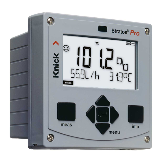
User Interface, Keypad MEMO SENS 1 Display 2 Keypad 3 Rating plate (enclosure bottom) Function • Return to last menu level • Directly to measuring mode (press > 2 s) • Measuring mode: other display • Retrieve information • Show error messages •... -
Page 22: Display
Display MEMO SENS 1 Temperature 13 Info available 2 Sensocheck 14 Hold mode active 3 Interval/response time 15 Main display 4 Sensor data 16 Secondary display 5 Not used 17 Proceed using enter 6 Limit message: 18 ISM sensor Limit 1 or Limit 2 19 Diagnostics 7 Alarm... -
Page 23: Measuring Mode
Measuring Mode After the operating voltage has been connected, the analyzer auto- matically goes to “Measuring“ mode. To call the measuring mode from another operating mode (e.g. Diagnostics, Service): Hold meas key depressed (> 2 s). Sensoface indicator Active (sensor status) parameter set (configuration) Time... -
Page 24: Selecting The Mode / Entering Values
Selecting the Mode / Entering Values To select the operating mode: 1) Hold meas key depressed (> 2 s) (directly to measuring mode) 2) Press menu key: the selection menu appears 3) Select operating mode using left / right arrow key 4) Press enter to confirm the selected mode Selection menu Selected mode... - Page 25 Display in Measuring Mode The MAIN DISPLAY is the display which is shown in measuring mode. To call the measuring mode from any other mode, hold the meas key depressed for at least 2 sec. meas key enter key By pressing meas briefly you can step through further displays such as tag number (TAG) or flow (L/h).
-
Page 26: Color-Coded User Interface
Color-Coded User Interface The color-coded user interface guarantees increased operating safety. Operating modes are clearly signaled. The normal measuring mode is white. Information text appears on a green screen and the diagnostic menu appears on turquoise. The orange HOLD mode (e.g. during calibration) is quickly visible as is the magenta screen which indicates asset management messages for predictive diagnostics –... -
Page 27: Operating Modes
Operating Modes Diagnostics Display of calibration data, display of sensor data, performing a device self-test, viewing the logbook entries, display of hardware/software ver- sions of the individual components. The logbook can store 100 events (00...99). They can be displayed directly on the device. The logbook can be extended to 200 entries using a TAN (Option). -
Page 28: Menu Structure Of Modes And Functions
Menu Structure of Modes and Functions Meas. mode TAG display CLK display (main display selectable) after 60 s after 60 s Pressing the menu key (down arrow) opens the selection menu. Select the menu group using the left/right arrow keys. Pressing enter opens a menu item. -
Page 29: Hold Mode
HOLD Mode The HOLD mode is a safety state during configuration and calibration. Output current is frozen (LAST) or set to a fixed value (FIX). The HOLD mode is indicated by orange display backlighting. HOLD mode, display icon: Output signal response •... -
Page 30: Alarm
Alarm External activation of HOLD The HOLD mode can be activated from outside by sending a signal to the HOLD input (e.g. from the process control system). Power supply HOLD 12...24 V AC/DC input Process control system HOLD inactive 0...2 V AC/DC HOLD active 10...30 V AC/DC Manual activation of HOLD... -
Page 31: Alarm And Hold Messages
Alarm and HOLD Messages Message Released by Cause Alarm Sensocheck Polarization / Cable (22 mA) Error messages Flow (CONTROL input) HOLD HOLD HOLD via menu or input (Last/Fix) CONF Configuration Calibration SERVICE Service Generating a message via the CONTROL input (min. -
Page 32: Configuration
Configuration Menu Structure of Configuration The device provides 2 parameter sets “A“ and “B“. By switching between the param- eter sets you can adapt the device to different measurement situations, for example. Parameter set “B“ only permits setting of process-related parameters. The configuration steps are assigned to different menu groups. - Page 33 Configuration Parameter set A/B: configurable menu groups The device provides 2 parameter sets “A“ and “B“. By switching between the param- eter sets you can adapt the device to different measurement situations, for example. Parameter set “B“ only permits setting of process-related parameters. Menu group Parameter set A Parameter set B...
-
Page 34: Manual Switchover Of Parameter Sets A/B
Configuration Manual switchover of parameter sets A/B Display Action Remark To switch between Manual selection of parameter sets must have parameter sets: been preset in CONFIG Press meas. mode. Default setting is a fixed parameter set A. Wrong settings change the measurement properties! PARSET blinks in the... - Page 35 Configuration Configuration Choices Default Sensor (SENSOR) (EXT only with I-input enabled via TAN) (EXT only with I-input enabled via TAN) Note: Pressing info dis- plays nominal buffer val- ues + manufacturer (For specifiable buf- Enter values for buffer 1 fer set, see Appendix: Enter values for buffer 2 “Buffer Tables“)
- Page 36 Configuration Configuration Choices Default Output 1 (OUT1) Select °C / °F at “Sensor“ FILTERTIME 0...120 SEC 0000 SEC 22mA FAIL ON/OFF 22mA FACE ON/OFF HOLD MODE LAST/FIX LAST HOLD-FIX 4...22 mA 021.0 mA Output 2 (OUT2) Select °C / °F at “Sensor“ FILTERTIME 0...120 SEC 0000 SEC 22mA FAIL ON/OFF 22mA FACE...
- Page 37 Configuration Configuration Choices Default Temperature compensation (CORRECTION) Table with 20 user-definable values, 5 °C step size Control input (CNTR_IN) Parameter-set CONTROL switchover (PARSET) flow measurement (FLOW) FLOW FLOW ADJUST 12000 0 ... 20000 pulses/liter pulses/liter Alarm (ALARM) ALA: DELAYTIME 0...600 SEC 0010 SEC SENSOCHECK ON/OFF...
- Page 38 Configuration Configuration Choices Default Parameter set (PARSET) Select fixed parameter set (A) PARSET FIX A/ PARSET FIX A or switch between A/B via CNTR INPUT / (fixed parameter control input or manually in MANUAL set A) measuring mode Real-time clock (CLOCK) CLK: FORMAT 24 h / 12 h...
- Page 39 Configuration Support of Pfaudler Sensors This requires an additional function (TAN). The option is enabled in the SERVICE / OPT: PFAUDLER menu (see page 103). When you use a Memosens Pfaudler sensor, the data will be read from the sensor or will be set to standard values.
-
Page 40: Configuration (Template For Copy)
Configuration (Template for Copy) Parameters Parameter set A Parameter set B SNS: Sensor type SNS: Temperature unit SNS: Measurement temp SNS: Manual meas. temp SNS: Calibration temp SNS: Manual cal temp SNS: Calibration mode SNS: Buffer set selection SNS: Calibration timer SNS: Calibration cycle SNS: ISM adaptive cal timer (ACT) - Page 41 Configuration (Template for Copy) Parameter Parameter set A Parameter set B OT2: Process variable OT2: Current start OT2: Current end OT2: Filter time OT2: FAIL 22 mA (error messages) OT2: FACE 22 mA (Sensoface messages) OT2: HOLD mode OT2: HOLD FIX current COR: Temp coefficient COR: Ext.
-
Page 42: Sensor
Configuration Sensor Select: sensor type, temperature unit, temp detection during measurement 1) Press menu key. 2) Select CONF using keys, press enter. 3) Select parameter set using , press enter. 4) Select SENSOR menu using keys, press enter. 5) All items of this menu group are indicated by the “SNS:”... - Page 43 Configuration Menu item Action Choices Select sensor type Select sensor type using keys. Press enter to confirm. Temperature unit Select °C or °F using keys. Press enter to confirm. Temp detection Select mode using keys: during measurement AUTO: Measured by sensor MAN: Direct input of...
- Page 44 Configuration Sensor Select: temp detection during calibration, calibration mode 1) Press menu key. 2) Select CONF using keys, press enter. 3) Select parameter set using , press enter. 4) Select SENSOR menu using keys, press enter. 5) All items of this menu group are indicated by the “SNS:”...
- Page 45 Configuration Menu item Action Choices Temp detection Select mode using keys: during calibration AUTO: Measured by sensor MAN: Direct input of temperature, no measure- ment (see next step) EXT: Temperature speci- fied via current input (only if TAN E enabled) Press enter to confirm.
- Page 46 Configuration Sensor Adjust: Cal timer, cal cycle 1) Press menu key. 2) Select CONF using keys, press enter. 3) Select parameter set using , press enter. 4) Select SENSOR menu using keys, press enter. 5) All items of this menu group are indicated by the “SNS:”...
- Page 47 Configuration Menu item Action Choices Calibration timer Adjust CALTIMER using keys: OFF: No timer With ADAPT, the calibra- ADAPT: Maximum cal tion cycle is automatically cycle (adjust in the next reduced depending on step) the sensor load (high FIX: Fixed cal cycle (adjust temperatures and pH in the next step) values) and for digital...
- Page 48 Configuration Sensor Adjust: CIP cleaning cycles, SIP sterilization cycles 1) Press menu key. 2) Select CONF using keys, press enter. 3) Select parameter set using , press enter. 4) Select SENSOR menu using keys, press enter. 5) All items of this menu group are indicated by the “SNS:”...
- Page 49 Configuration Menu item Action Choices CIP / SIP Cleaning cycles Select ON or OFF using keys. On / Off Activates/deactivates log- ging in extended logbook and counters (if provided) Press enter to confirm. Cleaning cycles Only with CIP COUNT ON: Enter value using ...
- Page 50 Configuration Sensor Adjust: Autoclaving counter 1) Press menu key. 2) Select CONF using keys, press enter. 3) Select parameter set using keys, press enter. 4) Select SENSOR menu using keys, press enter. 5) All items of this menu group are indicated by the “SNS:”...
- Page 51 Configuration Autoclaving Counter After reaching a specified limit value the autoclaving counter gen- erates a Sensoface message. As soon as the counter has reached the specified value, Sensoface is getting “sad”. Pressing the info key shows the text “AUTOCLAVE CYCLES OVERRUN” which reminds you that the maximum number of autoclaving cycles has been reached.
-
Page 52: Sensor Verification (Tag, Group)
Configuration Memosens Sensor Sensor Verification (TAG, GROUP) 1) Press menu key. 2) Select CONF using , press enter. 3) Select parameter set using keys, press enter. 4) Select SENSOR menu using keys, press enter. 5) All items of this menu group are indicated by the “SNS:”... - Page 53 Configuration Menu item Action Choices Select ON or OFF using ON/OFF keys. Press enter to confirm. When switched on, the entry for “TAG” in the Memosens sensor is com- pared to the entry in the analyzer. If the entries differ, a mes- sage will be generated.
-
Page 54: Current Output 1
Configuration Current Output 1 Output current range. Current start, Current end. 1) Press menu key. 2) Select CONF using keys, press enter. 3) Select parameter set using keys, press enter. 4) Select OUT1 menu using keys, press enter. - Page 55 Configuration Menu item Action Choices Process variable Select using keys: PH: pH value ORP: Redox potential TMP: Temperature Press enter to confirm. Current start Modify digit using keys, select next digit using keys. Press enter to confirm. Current end Enter value using ...
- Page 56 Configuration Current Output 1 Adjusting the time interval of the output filter 1) Press menu key. 2) Select CONF using keys, press enter. 3) Select parameter set using keys, press enter. 4) Select OUT1 menu using keys, press enter.
- Page 57 Configuration Menu item Action Choices Time averaging filter Enter value using keys. Press enter to confirm. Time averaging filter To smoothen the current output, a low-pass filter with adjustable filter time constant can be switched on. When there is a jump at the input (100 %), the output level is at 63 % after the time interval has been reached.
- Page 58 Configuration Current Output 1 Output current for error message or Sensoface alert 1) Press menu key. 2) Select CONF using keys, press enter. 3) Select parameter set using keys, press enter. 4) Select OUT1 menu using keys, press enter.
- Page 59 Configuration Menu item Action Choices Output current for In the case of an error (FAIL), the current output is error message (FAIL) set to 22 mA. Select ON or OFF using keys. Press enter to confirm. Output current for In the case of a Sensoface alert (FACE), the current Sensoface (FACE)
- Page 60 Configuration Current Output 1 Output current during HOLD 1) Press menu key. 2) Select CONF using keys, press enter. 3) Select parameter set using keys, press enter. 4) Select OUT1 menu using keys, press enter. 5) All items of this menu group are indicated by the “OT1:”...
- Page 61 Configuration Menu item Action Choices Output current LAST/FIX LAST: During HOLD the last measured value is during HOLD maintained at the output. FIX: During HOLD a value (to be entered) is main- tained at the output. Select using Press enter to confirm. Output current for Only with FIX selected: 00.00...22.00 mA...
-
Page 62: Current Output 2
Configuration Current Output 2 Process variable. Current start. Current end ... 1) Press menu key. 2) Select CONF using keys, press enter. 3) Select parameter set using keys, press enter. 4) Select OUT2 menu using keys, press enter. - Page 63 Configuration Menu item Action Choices Process variable Select using keys: PH: pH value ORP: Redox potential TMP: Temperature Press enter to confirm. All the following adjustments are made as for current output 1 (see there)!
-
Page 64: Temperature Compensation
Configuration Temperature Compensation TC process medium: Linear or user-definable table 1) Press menu key. 2) Select CONF using keys, press enter. 3) Select parameter set using keys, press enter. 4) Select CORRECTION menu using keys, press enter. 5) All items of this menu group are indicated by the “COR:”... - Page 65 Configuration Menu item Action Choices Temperature For pH measurement only: Select temperature compensation, compensation of the process medium process medium. Linear: LIN Table: USERTAB Select using key, confirm by pressing enter. Temperature Enter the linear tempera- ture compensation of the compensation, linear process medium.
- Page 66 Configuration Temperature Compensation Current input, external temp measurement 1) Press menu key. 2) Select CONF using keys, press enter. 3) Select parameter set using keys, press enter. 4) Select CORRECTION menu using keys, press enter. 5) All items of this menu group are indicated by the “COR:”...
- Page 67 Configuration Menu item Action Choices Current input, Only if enabled via TAN and selected during con- external temp figuration (SENSOR). measurement Select ON or OFF using keys. Press enter to confirm. Current range Select desired range using keys. Press enter to confirm.
-
Page 68: Control Input
Configuration CONTROL Input Parameter set selection via external signal or flow measurement 1) Press menu key. 2) Select CONF using keys, press enter. 3) Select parameter set using , press enter. 4) Select CNTR_IN menu using keys, press enter. - Page 69 Configuration Menu item Action Choices Select function of PARSET Select using keys. (selecting parameter Press enter to confirm. CONTROL input set A/B via signal at CONTROL input) Flow (for connecting a pulse- output flow meter) Adjust to flow meter: With “Flow”...
-
Page 70: Alarm Settings
Configuration Alarm Settings Alarm delay. Sensocheck. 1) Press menu key. 2) Select CONF using keys, press enter. 3) Select parameter set using , press enter. 4) Select ALARM menu using keys, press enter. 5) All items of this menu group are indicated by the “ALA:”... - Page 71 Configuration Menu item Action Choices Alarm delay 0...600 SEC Enter value using (010 SEC) keys. Press enter to confirm. Sensocheck Select Sensocheck ON/OFF (continuous monitoring of glass and reference electrode) Select ON or OFF using keys. Press enter to confirm. (At the same time, Sensoface is activated.
- Page 72 Configuration Alarm Settings CONTROL input (FLOW MIN, FLOW MAX) 1) Press menu key. 2) Select CONF using keys, press enter. 3) Select parameter set using , press enter. 4) Select ALARM menu using keys, press enter. 5) All items of this menu group are indicated by the “ALA:”...
- Page 73 Configuration Menu item Action Choices CONTROL input The CONTROL input can generate an alarm when assigned to FLOW (flow monitoring) in the CONF menu: FLOW CNTR Flow measurement: allows monitoring the minimum and maximum flow (pulse counter) Alarm Specify value Default: 05.00 liters/h Minimum flow FLOW MIN...
-
Page 74: Time And Date
Configuration Time and Date Measuring Points (TAG/GROUP) 1) Press menu key. 2) Select CONF using , press enter. 3) Select parameter set A using keys, press enter. 4) Select CLOCK or TAG using keys, press enter. 5) All items of this menu group are indicated by the “CLK:”... - Page 75 Configuration Time and Date Control of the calibration and cleaning cycles is based on the time and date of the integrated real-time clock. In measuring mode the time is shown in the lower display. When using digital sensors, the calibration data is written in the sensor head. In addition, the logbook entries (cf Diagnostics) are provided with a time stamp.
-
Page 76: Digital Sensors
Settings and Currently connected sensor: specifications Sensor type, manufacturer, order code and serial number Sensor type: pH (glass) Order code: SE 533X/1-NMSN Manufacturer: KNICK Serial number: 1030550 Function selection StartCenter Calibration Table View History Statistics pH Buffers (The selected function is highlighted.) -
Page 77: Memosens Sensors: Configuring The Device
Calibration history of several sensors function) or “Advanced“ (with sensor database) version: www.knick.de History: Load diagrams of the sensors Memosens Sensors: Configuring the Device The sensor type is selected during Configuration. The device only switches to measuring mode when the connected sensor corresponds to the type configured (Sensoface is friendly): Otherwise, an error message is released. -
Page 78: Replacing A Sensor
Digital Sensors Connecting a Digital Sensor Step Action/Display Remark Connect sensor Before a digital sensor is connected, the error message “No sensor“ is displayed. Wait until the The hourglass in the display blinks. sensor data are MEMO SENS displayed. Check sensor Display color changes to green. - Page 79 Digital Sensors Step Action/Display Remark Press menu key to call Select HOLD Now the device is in HOLD mode. The HOLD mode can also mode the selection menu, be activated externally via the select HOLD using the HOLD input. During HOLD the keys, press enter output current is frozen at its last to confirm.
-
Page 80: Calibration
Calibration Note: • All calibration procedures must be performed by trained person- nel. Incorrectly set parameters may go unnoticed, but change the measuring properties. • The response time of the sensor and temperature probe is considerably reduced when the sensor is first moved about in the buffer solution and then held still. -
Page 81: Selecting A Calibration Mode
Selecting a Calibration Mode Calibration is used to adapt the device to the individual sensor characteristics, namely asymmetry potential and slope. Access to calibration can be protected with a passcode (SERVICE menu). First, you open the calibration menu and select the calibration mode: CAL_PH Depending on configuation setting: AUTO... -
Page 82: Zero Adjustment (Isfet)
Zero adjustment Zero Adjustment (ISFET) This adjustment allows the use of ISFET sensors with differing nomi- nal zero (pH only). The function is available when Sensor selection = MEMOSENS has been set during configuration. Zero adjustment is disabled for any other sensors. The adjustment is made using a zero buffer (pH 7.00). - Page 83 Zero Adjustment (ISFET) Display Action Remark At the end of the ad- This is not the final justment procedure calibration value of the zero offset [mV] of the sensor! Asym- the sensor is displayed metry potential (based on 25 °C). and slope must be Sensoface is active.
-
Page 84: Automatic Calibration (Calimatic)
Adjustment (Calimatic) Automatic Calibration (Calimatic) The AUTO calibration mode and the type of temperature detection are selected during configuration. Make sure that the buffer solutions used correspond to the configured buffer set. Other buffer solutions, even those with the same nominal values, may demonstrate a differ- ent temperature response. - Page 85 Automatic Calibration (Calimatic) Display Action Remark Note: At the end of the stabil- ity check, the value will Stability check can be saved and the asym- be stopped after metry potential will be 10 sec (by pressing displayed. enter). However, this Calibration with the first reduces calibration buffer is terminated.
-
Page 86: Manual Calibration With Buffer Entry
Manual Calibration with Buffer Entry The MAN calibration mode and the type of temperature detection are selected during configuration. For calibration with manual buffer specification, you must enter the pH value of the buffer solution used in the device for the proper temperature. Any desired buffer solution can be used for calibration. - Page 87 Manual Calibration with Buffer Entry Display Action Remark Note: At the end of the stabil- ity check, the value will Stability check can be saved and the asym- be stopped after metry potential will be 10 sec (by pressing enter). However, this displayed.
-
Page 88: Data Entry Of Premeasured Sensors
Data Entry of Premeasured Sensors The DAT calibration mode must have been preset during configuration. You can directly enter the values for slope and asymmetry potential of a sensor. The values must be known, e.g. determined beforehand in the laboratory. Display Action Remark... - Page 89 Converting Slope to mV Converting slope [%] to slope [mV/pH] at 25 °C mV/pH 46.2 47.4 48.5 49.7 50.9 52.1 53.3 54.5 55.6 56.8 58.0 100 59.2 102 60.4 Converting asymmetry potential to sensor zero point [mV] ZERO = 7 - = Sensor zero ZERO S [mV / pH]...
-
Page 90: Product Calibration (Ph)
Product calibration Product Calibration (pH) Calibration by sampling (one-point calibration). During product calibration the sensor remains in the process. The measurement process is only interrupted briefly. Procedure: 1) The sample is measured in the lab or directly on the site using a por- table meter. - Page 91 Product Calibration (pH) Display Action Remark The device returns to From the blinking measuring mode. CAL mode indicator you see that product calibration has not been terminated. Product calibration Display (3 sec) step 2 Now the device is in HOLD mode. The stored value is displayed (blinking) and can be overwritten with...
-
Page 92: Orp (Redox) Calibration
ORP (Redox) Calibration The potential of a redox sensor is calibrated using a redox (ORP) buffer solution. In the course of that, the difference between the measured potential and the potential of the calibration solution is determined according to the following equation. During measurement this differ- ence is added to the measured potential. - Page 93 ORP Calibration Display Action Remark Select ORP calibration, proceed with enter Remove the sensor and Display (3 sec) temperature probe, Now the device is in clean them, and im- HOLD mode. merse them in the redox buffer. Enter setpoint value for redox buffer.
-
Page 94: Temp Probe Adjustment
Temp probe adjustment Temp Probe Adjustment Display Action Remark Select temp adjust- Wrong settings ment. Press enter to change the proceed. measurement properties! Measure the tempera- Display (3 sec) ture of the process me- Now the device is in dium using an external HOLD mode. -
Page 95: Measurement
Measurement Display Remark From the configuration or calibration menus, you can switch the device to measuring mode by pressing the meas key. In the measuring mode the upper display shows the configured process variable (pH, or AM/PM and °F: ORP [mV], or temperature), the lower dis- play line shows the time and the second configured process variable (pH, ORP [mV], or temperature). -
Page 96: Diagnostics
Diagnostics (DIAG) Diagnostics In the Diagnostics mode you can access the following menus without interrupting the measurement: CALDATA Viewing the calibration data SENSOR Viewing the sensor data SELFTEST Starting a device self-test LOGBOOK Viewing the logbook entries MONITOR Displaying currently measured values VERSION Displaying device type, software version, serial number Access to diagnostics can be protected with a passcode... - Page 97 Diagnostics Display Menu item Display of calibration data Select CALDATA using, confirm with enter. Use thekeys to select the desired parameter from the bottom line of the display (LAST_CAL ISFET-ZERO ZERO SLOPE NEXT_CAL). The selected parameter is shown in the main display. Press meas to return to measurement.
- Page 98 Diagnostics Display Menu item Device self-test (To abort, you can press meas.) 1) Display test: Display of all segments with changing background colors (white/green/red). Press enter to proceed. 2) RAM test: Hourglass blinks, then display of --PASS-- or --FAIL-- Press enter to proceed. 3) EEPROM test: Hourglass blinks, then display of --PASS-- or --FAIL-- Press enter to proceed.
- Page 99 Diagnostics Display Menu item Displaying the logbook entries Select LOGBOOK using, press enter to confirm. Using the keys, you can scroll backwards and forwards through the logbook (entries -00-...-99-), -00- being the last entry. If the display is set to date/time, you can search for a particular date using the ...
- Page 100 Diagnostics Display Menu item Displaying the currently measured values (sensor monitor) Select MONITOR using, press enter to confirm. Use the keys to select the desired parameter from the bottom line of the display: mV_PH mV_ORP RTD R_GLASS R_REF I-INPUT (for digital sensors also: OPERATION TIME SENSOR WEAR LIFETIME CIP SIP AUTOCLAVE, for ISM sensors in addition: ACT (adaptive calibration timer)
-
Page 101: Service
Service (SERVICE) A Service In the Service mode you can access the following menus: MONITOR Displaying currently measured values SENSOR Resetting TTM (ISM only ), incrementing the autoclaving counter OUT1 Testing current output 1 OUT2 Testing current output 2 CODES Assigning and editing passcodes DEFAULT Resetting the device to factory settings... - Page 102 Service Menu item Remark Displaying currently measured values (sensor monitor) with HOLD mode activated: Select MONITOR using, press enter to confirm. Select variable in the bottom text line using. The selected parameter is shown in the upper dis- play line. Display example: As the device is in HOLD mode, you can perform validations using simulators without influencing the...
- Page 103 Service Menu item Remark Assigning passcodes: In the “SERVICE - CODES“ menu you can assign pass- codes to DIAG, HOLD, CAL, CONF and SERVICE modes (Service preset to 5555). When you have lost the Service passcode, you have to request an “Ambulance TAN“ from the manufac- turer specifying the serial number of your device.
-
Page 104: Operating States
Operating States Operating status Measuring DIAG 60 s CONF SERVICE SERVICE OUT 1 SERVICE OUT 2 HOLD Explanation: as configured (Last/Fix or Last/Off ) active manual... - Page 105 A2...X: Supply Units and Connection Recommended Power Supply Units: Order No.: Repeater power supply, Ex, 90...253 V AC, WG 21 A7 output 4...20 mA Repeater power supply, Ex, 90...253 V AC, WG 21 A7 Opt. 470 HART, output 4...20 mA Repeater power supply, Ex, 24 V AC/DC, WG 21 A7 Opt.
-
Page 106: Product Line And Accessories
Product Line and Accessories Order Code Stratos Pro A 2... Example MSPH 2-wire / 4-20 mA B,C,E Communication Without (HART retrofittable via TAN) 0 Version number Version Approvals General Safety ATEX / IECEx Zone 2 ATEX / IECEx / FM / CSA Zone 1 / Cl 1 Div 1 Measuring channel Memosens pH / Redox digital... -
Page 107: Specifications
Manual calibration with entry of individual buffer values Data entry of pre-measured electrodes Product calibration Calimatic buffer sets -01- Mettler-Toledo 2.00/4.01/7.00/9.21 -02- Knick CaliMat 2.00/4.00/7.00/9.00/12.00 -03- Ciba (94) 2.06/4.00/7.00/10.00 -04- NIST technical 1.68/4.00/7.00/10.01/12.46 -05- NIST standard 1.679/4.006/6.865/9.180 -06- HACH 4.01/7.00/10.01... - Page 108 Specifications I input (TAN) Current input 0/4 ... 20 mA / 50 Ω for external temperature signal Start/end of scale Configurable –20 ... +200 °C (-4 ... +392 °F) Characteristic Linear Measurement error 1.3) < 1% current value + 0.1 mA HOLD input Galvanically separated (optocoupler) Function...
- Page 109 Specifications Output 2 Current loop, 4 ... 20 mA, floating, protected against inverse polarity Supply voltage 14 ... 30 V Process variable * pH, ORP or temperature Overrange * 22 mA in the case of error messages Output filter * filter, time constant 0 ...
- Page 110 Assigning passcodes for menu access Factory setting Resetting all parameters to factory setting Enabling optionally available additional functions Explosion protection See Control Drawing or www.knick.de (A2**B/X) Data retention Parameters, calibration data, logbook > 10 years (EEPROM) EN 61326-1 (General Requirements)
- Page 111 Specifications Enclosure Molded enclosure made of glass-reinforced PBT, PC Mounting Wall, pipe/post or panel mounting Color Gray, RAL 7001 Ingress protection IP 67, NEMA 4X Flammability UL 94 V-0 Dimensions 148 mm x 148 mm Control panel cutout 138 mm x 138 mm to DIN 43 700 Weight Approx.
-
Page 112: Buffer Tables
Buffer Tables -01- Mettler-Toledo (corresponds to former “Knick technical buffers”) °C 2.03 4.01 7.12 9.52 2.02 4.01 7.09 9.45 2.01 4.00 7.06 9.38 2.00 4.00 7.04 9.32 2.00 4.00 7.02 9.26 2.00 4.01 7.00 9.21 1.99 4.01 6.99 9.16 1.99 4.02... - Page 113 Buffer Tables -02- Knick CaliMat (Merck Titrisols, Riedel-de-Haen Fixanals) °C Order No. CS-P0200A/... CS-P0400A/... CS-P0700A/... CS-P0900A/... CS-P1200A/... 2.01 4.05 7.09 9.24 12.58 2.01 4.04 7.07 9.16 12.39 2.01 4.02 7.04 9.11 12.26 2.00 4.01 7.02 9.05 12.13 2.00 4.00 7.00 9.00...
- Page 114 Buffer Tables -03- Ciba (94) buffers Nominal values: 2.06 4.00 7.00 10.00 °C 2.04 4.00 7.10 10.30 2.09 4.02 7.08 10.21 2.07 4.00 7.05 10.14 2.08 4.00 7.02 10.06 2.09 4.01 6.98 9.99 2.08 4.02 6.98 9.95 2.06 4.00 6.96 9.89 2.06 4.01...
- Page 115 Buffer Tables -04- NIST technical buffers °C 1.67 4.00 7.115 10.32 13.42 1.67 4.00 7.085 10.25 13.21 1.67 4.00 7.06 10.18 13.01 1.67 4.00 7.04 10.12 12.80 1.675 4.00 7.015 10.06 12.64 1.68 4.005 7.00 10.01 12.46 1.68 4.015 6.985 9.97 12.30 1.69...
- Page 116 Buffer Tables -05- NIST standard buffers NIST Standard (DIN 19266 : 2015-05) °C 1.666 4.000 6.984 9.464 1.668 3.998 6.951 9.395 13.207 1.670 3.997 6.923 9.332 13.003 1.672 3.998 6.900 9.276 12.810 1.675 4.000 6.881 9.225 12.627 1.679 4.005 6.865 9.180 12.454 1.683...
- Page 117 Buffer Tables -06- HACH buffers Nominal values: 4.01 7.00 10.01 (± 0.02 at 25 °C) °C 4.00 7.118 10.30 4.00 7.087 10.23 4.00 7.059 10.17 4.00 7.036 10.11 4.00 7.016 10.05 4.01 7.000 10.01 4.01 6.987 9.96 4.02 6.977 9.92 4.03 6.970 9.88...
- Page 118 Buffer Tables -07- WTW technical buffers °C 2.03 4.01 7.12 10.65 2.02 4.01 7.09 10.52 2.01 4.00 7.06 10.39 2.00 4.00 7.04 10.26 2.00 4.00 7.02 10.13 2.00 4.01 7.00 10.00 1.99 4.01 6.99 9.87 1.99 4.02 6.98 9.74 1.98 4.03 6.97 9.61...
- Page 119 Buffer Tables -08- Hamilton Duracal buffers °C 1.99 4.01 7.12 10.23 12.58 1.99 4.01 7.09 10.19 12.46 2.00 4.00 7.06 10.15 12.34 2.00 4.00 7.04 10.11 12.23 2.00 4.00 7.02 10.06 12.11 2.00 4.01 7.00 10.01 12.00 1.99 4.01 6.99 9.97 11.90 1.98...
- Page 120 Buffer Tables -09- Reagecon buffers °C 0°C *2.01 *4.01 *7.07 *9.18 *12.54 5°C *2.01 *4.01 *7.07 *9.18 *12.54 10°C 2.01 4.00 7.07 9.18 12.54 15°C 2.01 4.00 7.04 9.12 12.36 20°C 2.01 4.00 7.02 9.06 12.17 25°C 2.00 4.00 7.00 9.00 12.00 30°C...
- Page 121 Buffer Tables -10- DIN 19267 buffers...
-
Page 122: U1- Specifiable Buffer Set
-U1- Specifiable Buffer Set You can specify a buffer set with 2 buffer solutions in the temperature range of 0 ... 95 °C, step width: 5 °C. To do so, select buffer set -U1- in the configuration menu. As delivered, the Ingold technical buffer solutions pH 4.01 / 7.00 are stored as buffer set and can be edited. - Page 123 -U1- Specifiable Buffer Set Step Action/Display Remark Select buffer set -U1- (CONFIG / SNS menu) Select buffer solution You are prompted for confirmation to prevent 1 for editing accidental changes of the settings. Select “YES“ using up/ down key. Editing the values of Enter the values for the first buffer solution in buffer solution 1...
- Page 124 -U1- Specifiable Buffer Set Buffer Set U1: Fill in your configuration data or use the table as original for copy. Temperature (°C) Buffer 1 Buffer 2...
-
Page 125: Error Handling
Error Handling Alarm condition: • The display backlighting turns red • The alarm icon is displayed • The complete measured-value display blinks • “ERR xxx“ is displayed in the lower menu line Press the [info] key to view a short error text: •... -
Page 126: Error Messages
Error codes Error Messages Info text Problem (is displayed in case of Error Possible causes fault when the Info key is pressed) ERR 99 Error in factory settings DEVICE FAILURE EEPROM or RAM defective This error message only occurs in the case of a total defect. The device must be repaired and recalibrated at the factory. - Page 127 Error Messages Info text Problem (is displayed in case of Error Possible causes fault when the Info key is pressed) ERR 05 Error in cal data * CAL DATA ERR 10 ORP display range violation ORP RANGE < -1999 mV or > 1999 mV ERR 11 pH display range violation PH RANGE...
- Page 128 Error Messages Info text Problem (is displayed in case of Error Possible causes fault when the Info key is pressed) ERR 72 Flow too low FLOW TOO LOW ERR 73 Flow too high FLOW TOO HIGH ERR 100 Span Out1 configuration error INVALID SPAN OUT1 Selected span too small ERR 101...
-
Page 129: Sensoface
Sensoface (Sensocheck must have been activated during configuration.) The smiley in the display (Sensoface) alerts to sensor problems ( defective sensor, sensor wear, defective cable, maintenance request). The permitted calibration ranges and the conditions for a friendly, neutral, or sad Sensoface are summarized in the following table. Additional icons refer to the error cause. - Page 130 Sensoface Display Problem Status Asymmetry Asymmetry potential (zero) potential and and slope of the sensor are slope still okay. The sensor should be replaced soon. Asymmetry potential and slope of the sensor have reached values which no lon- ger ensure proper calibration. Replace sensor.
- Page 131 Sensoface Display Problem Status Sensor wear High temperatures and pH (for digital values have caused a wear of sensors only) over 80%. The sensor should be replaced soon. Wear is at 100%. Replace sensor. SENSOR WEAR Replace sensor CHANGE SENSOR (DLI) AUTOCLAVE CYCLES Maximally permitted number of auto- OVERRUN...
-
Page 132: Fda 21 Cfr Part 11
FDA 21 CFR Part 11 Conformity with FDA 21 CFR Part 11 In their directive “Title 21 Code of Federal Regulations, 21 CFR Part 11, Electronic Records; Electronic Signatures“ the American health agency FDA (Food and Drug Administration) regulates the production and processing of electronic documents for pharmaceutical devel- opment and production. -
Page 133: Index
Index Access code assignment 103 Access codes, table 144 Accessories 106 Activating an option 103 Adaptive maintenance timer: reset 102 Alarm 30 Alarm and HOLD messages 31 Alarm: setting a delay time 70 Alarm settings, CONTROL input 72 Ambulance TAN 103 Application in hazardous locations 10 Assembly 12 Asymmetry potential 89... - Page 134 Index Calibration, redox calibration 92 Calibration, temperature probe adjustment 94 Calibration timer 47 Calibration timer, Sensoface 130 Calibration, zero adjustment 83 Calimatic 84 CIP (cleaning cycles) 49 CIP, error message 131 Cleaning cycles 49 Cleaning cycles, ISM sensor: configuration 48 Configuration: alarm 70 Configuration: calibration mode 44 Configuration: calibration timer 46...
- Page 135 Index Data entry of premeasured sensors 88 Date and time (configuration) 74 Date and time (usage) 75 Date, display 95 Device self-test 98 Device type, display 100 Diagnostics 96 Diagnostics, calibration data 97 Diagnostics, device self-test 98 Diagnostics, general 27 Diagnostics, logbook 99 Diagnostics, sensor data 97 Diagnostics, sensor monitor 100...
- Page 136 Index FACE: Sensoface alert, 22 mA output current 59 FAIL: error message, 22 mA output current 59 FDA 21 CFR Part 11 132 FLASH test 98 FLOW 69 Flow measurement: alarm 72 Flow measurement: configuration 68 GROUP (measuring points) 75 HOLD: configuration 61 HOLD mode, description 29 HOLD mode, exit 29...
- Page 137 Index Memosens: configuring the device 77 Memosens: connection 78 Memosens, connection via RS-485 18 Memosens sensors: calibration and maintenance in the lab 76 Memosens sensors: operation and connection 76 Memosens, wiring example 20 MemoSuite software for calibrating Memosens sensors 76 Menu structure 28 Menu structure of configuration 32 Message via CONTROL input 31...
- Page 138 Index Pfaudler sensors 39 Pipe mounting 14 Power supply units 105 Predictive maintenance (Memosens) 77 Presetting pH calibration 81 Process variable for current output 1 54 Process variable for current output 2 62 Product calibration 90 Product line 106 Protective hood 14 Quickstart guides 3 RAM test 98 Rating plates 16...
- Page 139 Index Serial number, display 100 Service 101 Service, factory setting 103 Service, general 27 Service, incrementing the autoclaving counter 102 Service, output current, specify value 102 Service, passcode assignment 103 Service passcode lost 103 Service: reset TTM interval 102 Service, sensor monitor 102 Settings of U1 buffer set 124 Setting the passcodes 103 Signal colors 22, 26...
- Page 140 Index Temperature detection during measurement 42 Temperature detection for calibration 45 Temperature measurement via current input 67 Temperature probe adjustment 94 Terminal assignments 16 Terminal assignments, overview 11 Terminals 16 Time and date (configuration) 74 Time and date (usage) 75 Time averaging filter 57 Time, display 95 Trademarks 143...
- Page 141 Index...
-
Page 143: Trademarks
InPro® is a registered trademark of Mettler-Toledo AG. ISM® is a registered trademark of Mettler-Toledo AG. Memosens® is a registered trademark of Endress+Hauser Conducta GmbH and Knick Elektronische Messgeräte GmbH & Co. KG. HART® is a registered trademark of the HART Communication Foundation. -
Page 144: Passcodes
Configuration (CONF) Knick Elektronische Messgeräte GmbH & Co. KG Beuckestraße 22 14163 Berlin Germany Phone: +49 30 80191-0 Fax: +49 30 80191-200 Web: www.knick.de Email: info@knick.de Stratos Pro A2.. MSPH: pH Measurement 090814 with Memosens TA-212.115-MS-KNE04 20170831 Software version: 3.x...
Need help?
Do you have a question about the Stratos Pro A2 MSPH Series and is the answer not in the manual?
Questions and answers