Knick Stratos Pro A2 MSCONDI Series Instruction Manual
Hide thumbs
Also See for Stratos Pro A2 MSCONDI Series:
- Quick start manual (72 pages) ,
- User manual (144 pages) ,
- Quick start manual (72 pages)

Related Manuals for Knick Stratos Pro A2 MSCONDI Series


Summary of Contents for Knick Stratos Pro A2 MSCONDI Series
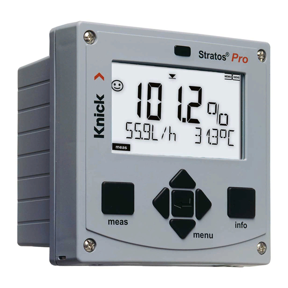
- Page 1 Stratos®Pro A2... MSCONDI Instruction Manual Latest Product Information: www.knick.de...
- Page 2 Warranty Warranty Defects occurring within 3 years from delivery date shall be remedied free of charge at our plant (carriage and insurance paid by sender). Sensors, fittings, and accessories: 1 year. Subject to change without notice. Return of Products Under Warranty Please contact our Service Team before returning a defective device.
-
Page 3: Documents Supplied
Spanish, Portuguese, Swedish, and Dutch. QuickStart ........27 More languages on CD-ROM and Быстрый старт ......39 Inicio rápido ........ 51 on our website: www.knick.de Início rápido ........ 63 Guida rapida ........ 75 • Installation and commissioning Snabbstart........87 QuickStart ........99 •... -
Page 4: Table Of Contents
Contents Documents Supplied ..............3 Introduction ..................7 Intended Use ..................7 Safety Information ................. 8 Overview of Stratos Pro A2... MSCONDI ........9 Assembly ..................10 Package Contents ................10 Mounting Plan, Dimensions ............11 Pipe Mounting, Protective Hood ..........12 Panel Mounting ..................13 Installation ..................14 Installation Instructions ..............14 Rating Plates / Terminal Assignments ........14... - Page 5 Contents Configuration (Original for Copy) ..........33 Sensor .....................36 Current Output 1 ................42 Current Output 2 ................48 Temperature Compensation ............50 Alarm Settings ..................54 Time and Date ..................56 Tag Number ....................56 Calibration ..................59 Selecting a Calibration Mode ............59 Calibration with Calibration Solution .........60 Calibration by Input of Cell Factor ..........62 Product Calibration ................63 Zero Calibration in Air / with Calibration Solution ....65...
- Page 6 Contents EC Declaration of Conformity ..........100 FDA 21 CFR Part 11 ..............101 Electronic Signature – Passcodes ..........101 Audit Trail ....................101 Index .....................102 Trademarks ..................111 Passcodes ..................112...
-
Page 7: Introduction
The device has been designed for application with electrodeless sensors of the SE 670 series (Knick). Plain-text messages in a large, backlit display allow intuitive opera- tion. The colored display backlighting signals alarm messages (red) or HOLD mode (orange). -
Page 8: Safety Information
Safety Information Safety information – Be sure to read and observe the following instructions! The device has been manufactured using state of the art technology and it complies with applicable safety regulations. When operating the device, certain conditions may nevertheless lead to danger for the operator or damage to the device. -
Page 9: Overview Of Stratos Pro A2
Overview Overview of Stratos Pro A2... MSCONDI + Output 1, 2 / HART Supply Output 1 RS 485 RS 485 A – Output 1 / HART RS 485 B GND/Shield Output 2 – Output 2 Current Input + Input – input HOLD HOLD... -
Page 10: Assembly
Assembly Package Contents Check the shipment for transport damage and completeness! The package should contain: • Front unit, rear unit, bag containing small parts • Specific test report • Documentation (cf Pg 3) • CD-ROM Fig.: Assembling the enclosure 1) Jumper (3 x) 6) Sealing insert (1 x) 2) Washer (1 x), for conduit 7) Rubber reducer (1 x) -
Page 11: Mounting Plan, Dimensions
Assembly Mounting Plan, Dimensions 1) Cable gland (3 x) 2) Knockouts for cable gland or ½" conduit, 21.5 mm dia. (2 knockouts) Conduits not included! 3) Knockout for pipe mounting (4 x) 4) Knockout for wall mounting (2 x) Fig.: Mounting plan (All dimensions in mm!) -
Page 12: Pipe Mounting, Protective Hood
Assembly Pipe Mounting, Protective Hood ø40...ø60 1) Hose clamp with worm gear drive to DIN 3017 (2 x) 2) Pipe-mount plate (1 x) 3) For vertical or horizontal posts or pipes 4) Self-tapping screw (4 x) Fig.: ZU 0274 pipe-mount kit (All dimensions in mm!) Fig.: ZU 0737 protective hood for wall and pipe mounting (All dimensions in mm!) -
Page 13: Panel Mounting
Assembly Panel Mounting <30 1) Circumferential sealing (1 x) 2) Screw (4 x) 3) Position of control panel 4) Span piece (4 x) 5) Threaded sleeve (4 x) Cutout 138 x 138 mm (DIN 43700) 1...22 Fig.: ZU 0738 panel-mount kit (All dimensions in mm!) -
Page 14: Installation
Installation Installation Instructions • Installation of the device must be carried out by trained experts in accordance with this instruction manual and as per applicable local and national codes. • Be sure to observe the technical specifications and input ratings during installation! •... -
Page 15: Wiring Of Stratos Pro A201/A211 Mscondi
Installation Wiring of Stratos Pro A201/A211 MSCONDI Areas for placing the screwdriver to pull out the terminals HART Terminal row 1 Terminal row 2 1 (BN) Supply hold 2 (GN) RS 485 A hold 3 (YE) RS 485 B n.c. 4 (WH) GND/shield contr. -
Page 17: Wiring Example: Se 670 (Via Rs-485)
Wiring Example: SE 670 (via RS-485) Measuring task: Conductivity, temperature Sensor: SE 670 Caution! Connection to RS-485 interface! The measuring module slot must be empty*! The SE 670 sensor is connected to the RS-485 interface of the device. When the SE 670 sensor is selected in the Configuration menu, the default values are taken as calibration data. -
Page 18: User Interface, Keypad
User Interface, Keypad 1 IrDA transmitter/receiver 2 Display 3 Keypad 4 Rating plate (bottom) Function meas • Return to last menu level • Directly to measuring mode (press > 2 s) info • Retrieve information • Show error messages enter •... -
Page 19: Display
Display 1 Temperature 13 Info available 2 Sensocheck 14 HOLD mode active 3 Interval/response time 15 Main display 4 Sensor data 16 Secondary display 5 Not used 17 Proceed with enter 6 Limit values 18 Not used 7 Alarm 19 Diagnostics 8 Service 20 Configuration mode 9 Parameter sets A/B... -
Page 20: Measuring Mode
Measuring Mode After the operating voltage has been connected and the sensor identi- fied, the device automatically goes to “Measuring“ mode. To call the measuring mode from another operating mode (e.g. Diagnostics, Service): Hold meas key depressed (> 2 s). Sensoface indicator Active parameter (sensor status) -
Page 21: Selecting The Mode / Entering Values
Selecting the Mode / Entering Values To select the operating mode: 1) Hold meas key depressed (> 2 s) (directly to measuring mode) 2) Press any arrow key: the selection menu appears 3) Select operating mode using left / right arrow key 4) Press enter to confirm the selected mode Selection menu Selected mode... -
Page 22: Operating Modes
Operating Modes Diagnostics Display of calibration data, display of sensor data, performing a device self-test, viewing the logbook entries, display of hardware/software versions of the individual components. The logbook can store 100 events (00...99). They can be displayed directly on the device. The logbook can be extended to 200 entries using a TAN (Option). -
Page 23: Menu Structure Of Modes And Functions
Menu Structure of Modes and Functions meas meas meas TAG display CLK display Measuring after 60 s after 60 s mode Pressing any arrow key opens the selection menu. Select the menu group using the left/right arrow keys. Press enter to open a menu. Press meas to return. ... -
Page 24: Hold Mode
HOLD Mode The HOLD mode is a safety state during configuration and calibration. Output current is frozen (Last) or set to a fixed value (Fix). The HOLD mode is indicated by orange display backlighting. HOLD mode, display icon: Output Signal Response •... -
Page 25: Alarm
Alarm External Activation of HOLD The HOLD mode can be activated from outside by sending a signal to the Hold input (e.g. from the process control system). Power supply HOLD 12...24 V AC/DC input Stratos Pro A2... Process control system (PCS) HOLD inactive 0...2 V AC/DC... -
Page 26: Configuration
Configuration Menu Structure of Configuration The device provides 2 parameter sets “A“ and “B“. By switching between the parameter sets you can adapt the device to different measurement situations, for example. Parameter set “B“ only permits setting of process-related parameters. The configuration steps are assigned to different menu groups. - Page 27 Configuration Parameter Set A/B: Configurable Menu Groups (Some parameters are identical in A and B. They are configured in parameter set A only.) Menu group Parameter set A Parameter set B SENSOR Sensor selection OUT1 Current output 1 Current output 1 OUT2 Current output 2 Current output 2...
-
Page 28: Parameter Set A/B
Configuration Parameter Set A/B Manual selection Display Action Remark To switch between Manual selection of parameter sets must have parameter sets: been preset in CONFIG Press meas mode. Default setting is a fixed parameter set A. Wrong settings change the measurement proper- ties! PARSET blinks in the lower line. - Page 29 Configuration Configuration Choices Default SENSOR SNS: SE 670 SE 670 SE 655* SE 656* SE 660* OTHER* OTHER* RTD TYPE 1000 PT 1000 PT 100 PT 30 NTC CELL FACTOR XX.XXx 01.980 TRANS RATIO XXX.Xx 120.00 *) These sensors appear in the menu selection but can only be used with a measuring module installed.
- Page 30 Configuration Configuration Choices Default SENSOR TEMP UNIT °C / °F °C TEMPERATURE AUTO AUTO EXT (only if enabled via TAN) TEMPERATURE –50...200 °C 025.0 °C (–58...392 °F) (077.0 °F) CIP COUNT ON/OFF SIP COUNT ON/OFF Configuration Choices Default Output 1 (OUT1) OT1: CHANNEL COND/TMP...
- Page 31 Configuration Configuration Choices Default Output 2 (OUT2) OT2: CHANNEL COND/TMP Begin: 0 °C End: 100 °C ... other steps like output 1 Temperature compensation (CORRECTION) COR: TC SELECT TC LIQUID 00.00...19.99%/K 00.00%/K I-INPUT 0...20 mA/4...20 mA 4...20 mA °C BEGIN 4 mA –50...200 °C 000.0 °C END 20 mA...
- Page 32 Configuration Configuration Choices Default Parameter set (PARSET) Select fixed parameter set PARSET FIX / PARSET FIX (A) or switch between A/B CNTR INPUT / (fixed parameter via control input or manu- MANUAL set A) ally in measuring mode Real-time clock (CLOCK) CLK: FORMAT 24 h / 12 h...
-
Page 33: Configuration (Original For Copy)
Configuration (Original for Copy) Default Settings of Parameter Sets Two complete parameter sets are stored in the EEPROM. As delivered, the two sets are identical but can be edited. Please note: Fill in your configuration data on the following pages or use them as original for copy. - Page 34 Configuration (Original for Copy) Parameter Parameter set A Parameter set B SNS: Sensor type Only with “Sensor type Others”: SNS: Type of temp probe SNS: Cell factor SNS: Transfer ratio SNS: Measuring mode SNS: Measuring range SNS: Concentration determination SNS: Temperature unit SNS: Temp detection SNS: Manual temp SNS: CIP counter...
- Page 35 (Original for Copy) Configuration Parameter Parameter set A Parameter set B OT2: Process variable OT2: LIN/LOG output OT2: Current start OT2: Current end OT2: Filter time OT2: 22 mA error current OT2: HOLD mode OT2: HOLD-FIX current COR: TC SELECT COR: Temp coefficient COR: Current range COR: Current start...
-
Page 36: Sensor
Configuration Sensor Selecting the parameters 1 Press any arrow key. 2 Select CONF using keys, press enter. 3 Select parameter set using keys, press enter. 4 Select SENSOR menu using keys, press enter. 5 All items of this menu group are indicated by the “SNS:”... - Page 37 Configuration Menu item Action Choices Select sensor type SE 670 Select SE 670 sensor using keys (default). SE 655 SE 656 SE 660 Press enter to confirm. OTHER Only with “OTHER“ (if Modify digit using keys, select next digit measuring module using ...
- Page 38 Configuration Sensor Select: Temperature unit, temperature detection, type of temp probe 1 Press any arrow key. 2 Select CONF using keys, press enter. 3 Select parameter set using keys, press enter. 4 Select SENSOR menu using keys, press enter.
- Page 39 Configuration Menu item Action Choices Temperature unit °C / °F Select °C or °F using keys. Press enter to confirm. Temp detection AUTO Select mode using keys: AUTO: Measured by sensor MAN: Direct input of temperature, no measure- ment (see next step) EXT: Temperature speci- fied via current input...
- Page 40 Configuration Sensor Adjust: Cleaning cycles, sterilization cycles 1 Press any arrow key. 2 Select CONF using keys, press enter. 3 Select parameter set using keys, press enter. 4 Select SENSOR menu using keys, press enter. 5 All items of this menu group are indicated by the “SNS:”...
- Page 41 Configuration Menu item Action Choices CIP / SIP Cleaning cycles Select ON or OFF using ON/OFF keys. On / Off Activates/deactivates log- ging in extended logbook Press enter to confirm. Sterilization cycles Select ON or OFF using ON/OFF keys. On / Off Activates/deactivates log- ging in extended logbook...
-
Page 42: Current Output 1
Configuration Current Output 1 Process variable, current start, current end 1 Press any arrow key. 2 Select CONF using keys, press enter. 3 Select parameter set using , press enter. 4 Select OUT1 menu using keys, press enter. 5 All items of this menu group are indicated by the “OT1:”... - Page 43 Configuration Menu item Action Remark Process variable Cond/TMP Select using keys: Cond: Conductivity TMP: Temperature Press enter to confirm. Select LIN/LOG: Selectable decades with Select using keys: logarithmic setting (LOG): LIN: Linear characteristic S/cm: 1.0 µS/cm, 10.0 µS/cm, LOG: Logarithmic –...
- Page 44 Configuration Current Output 1 Adjust time interval of output filter 1 Press any arrow key. 2 Select CONF using keys, press enter. 3 Select parameter set using keys, press enter. 4 Select OUT1 menu using keys, press enter. 5 All items of this menu group are indicated by the “OT1:”...
- Page 45 Configuration Menu item Action Choices Time averaging 0...120 SEC Enter value using (0000 SEC) keys. filter Press enter to confirm. Time Averaging Filter (Attenuation) To smoothen the current output, a low-pass filter with adjustable filter time constant can be switched on. When there is a jump at the input (100 %), the output level is at 63 % after the time interval has been reached.
- Page 46 Configuration Current Output 1 Output Current During Error and HOLD. 1 Press any arrow key. 2 Select CONF using keys, press enter. 3 Select parameter set using keys, press enter. 4 Select OUT1 menu using keys, press enter. 5 All items of this menu group are indicated by the “OT1:”...
- Page 47 Configuration Menu item Action Choices Output current Select ON or OFF using ON/OFF keys. during error message Press enter to confirm. Output current LAST/FIX LAST: During HOLD the last measured value is during HOLD maintained at the output. FIX: During HOLD a value (to be entered) is main- tained at the output.
-
Page 48: Current Output 2
Configuration Current Output 2 Output current range, process variable 1 Press any arrow key. 2 Select CONF using keys, press enter. 3 Select parameter set using keys, press enter. 4 Select OUT2 menu using keys, press enter. 5 All items of this menu group are indicated by the “OT2:”... - Page 49 Configuration Menu item Action Choices Process variable Cond/TMP Select using keys: Begin: 0 °C Cond: Conductivity End: 100°C TMP: Temperature Press enter to confirm. All the following adjustments are made as for current output 1 (see there)!
-
Page 50: Temperature Compensation
Configuration Temperature Compensation Selecting the compensation method 1 Press any arrow key. 2 Select CONF using keys, press enter. 3 Select parameter set using keys, press enter. 4 Select CORRECTION menu using keys, press enter. 5 All items of this menu group are indicated by the “COR:”... - Page 51 Configuration Menu item Action Choices Temperature Select desired compensa- tion using keys: compensation OFF: Temperature compensation switched LIN: Linear temperature compensation with entry of temperature coefficient nLF: Temperature compensation for natural waters to EN 27888 Press enter to confirm.
- Page 52 Configuration Temperature Compensation TC process medium, current input for temp measurement 1 Press any arrow key. 2 Select CONF using keys, press enter. 3 Select parameter set using keys, press enter. 4 Select CORRECTION menu using keys, press enter.
- Page 53 Configuration Menu item Action Choices Temp compensation, With linear compensation 0...19.99 %/K only: Enter temperature process medium compensation of the process medium. Enter value using keys. Press enter to confirm. Current range 4-20 mA / 0-20 mA Select desired range using ...
-
Page 54: Alarm Settings
Configuration Alarm Settings Delay, Sensocheck 1 Press any arrow key. 2 Select CONF using keys, press enter. 3 Select parameter set using keys, press enter. 4 Select ALARM menu using keys, press enter. 5 All items of this menu group are indicated by the “ALA:”... - Page 55 Configuration Menu item Action Choices Delay 0...600 SEC Enter value using (010 SEC) keys. Press enter to confirm. Sensocheck Select Sensocheck ON/OFF (continuous monitoring of sensor). Select ON or OFF using keys. Press enter to confirm. Error messages can be signaled by a 22 mA output current (see Error Messages and Configuration of Output 1/Output 2).
-
Page 56: Time And Date
Configuration Time and Date Tag Number 1 Press any arrow key. 2 Select CONF using keys, press enter. 3 Select parameter set A using keys, press enter. 4 Press enter. 5 Select CLOCK or TAG using keys, press enter. - Page 57 Configuration Time and Date Control of the calibration and cleaning cycles is based on the time and date of the integrated real-time clock. In measuring mode the time is shown in the lower display. When using digital sensors, the calibration data is written in the sensor head.
-
Page 59: Calibration
Calibration Please note: • All calibration procedures must be performed by trained person- nel. Incorrectly set parameters may go unnoticed, but change the measuring properties. Calibration can be performed by: • Determining the cell factor with a known calibration solution taking account of the temperature •... -
Page 60: Calibration With Calibration Solution
Calibration Calibration with Calibration Solution Input of temperature-corrected value of calibration solution with simultaneous display of cell factor. Be sure to use known calibration solutions and the respective temper- ature-corrected conductivity values (see calibration solution tables in the appendix). During the calibration procedure the temperature must be kept constant. - Page 61 Calibration Display Action Remark The cell factor and zero point are displayed. The “hourglass” icon is blinking. Use the arrow keys to select: • Repeat (repeat calibration) or • Measuring. Press enter to confirm. With MEAS selected: Display of measured End calibration by variable, Sensoface pressing enter.
-
Page 62: Calibration By Input Of Cell Factor
Calibration Calibration by Input of Cell Factor You can directly enter the value for the cell factor of a sensor. This value must be known, e.g. determined beforehand in the laboratory. The selected process variable and the temperature are displayed. This method is suitable for all process variables. -
Page 63: Product Calibration
Calibration Product Calibration (Calibration by sampling) For product calibration, the uncompensated conductivity (mS/cm, S/m) is used. During product calibration the sensor remains in the process. The measurement process is only interrupted briefly. Procedure: 1) The sample is measured in the lab or directly on the site using a portable meter. - Page 64 Calibration Display Action Remark The device returns to From the blinking measuring mode. CAL mode indicator you see that product calibration has not been terminated. Product calibration Display (3 sec) step 2: Now the device is in When the sample value HOLD mode.
-
Page 65: Zero Calibration In Air / With Calibration Solution
Calibration Zero Calibration in Air / with Calibration Solution Display Action Remark Select Calibration. Press enter to proceed. Select CAL_ZERO calibration method. Press enter to proceed. Ready for calibration. Display (3 sec) Hourglass blinks. Now the device is in HOLD mode. Calibration in air. -
Page 66: Temp Probe Adjustment
Temp probe adjustment Calibration Temp Probe Adjustment Display Action Remark Select Calibration. Wrong settings Press enter to proceed. change the Select CAL_RTD measurement calibration method. properties! Press enter to proceed. Measure the tempera- Display (3 sec) ture of the process Now the device is in medium using an HOLD mode. -
Page 67: Measurement
Measurement Display Remark From the configuration or calibration menus, you can switch the device to measuring mode by pressing the meas key. In the measuring mode the main display shows the configured process variable (Cond or AM/PM and °F: or temperature), the secondary display shows the time and the second configured process variable (Cond or temperature). -
Page 68: Diagnostics
Diagnostics (DIAG) Diagnostics In the Diagnostics mode you can access the following menus without interrupting the measurement: CALDATA Viewing the calibration data SENSOR Viewing the sensor data SELFTEST Starting a device self-test LOGBOOK Viewing the logbook entries MONITOR Displaying currently measured values VERSION Displaying device type, software version, serial number Access to diagnostics can be protected with a passcode... - Page 69 Diagnostics Menu item Remark Display of calibration data Select CALDATA using, press enter to confirm. Use thekeys to select the desired parameter from the bottom line of the display (LAST_CAL CELLFACTOR ZERO). The selected parameter is shown in the main display. Press meas to return to measurement.
- Page 70 Diagnostics Display Menu item Device self-test (To abort, you can press meas.) 1 Display test: Display of all segments with changing background colors white/green/red. Press enter to proceed. 2 RAM test: Hourglass blinks, then display of --PASS-- or --FAIL-- Press enter to proceed. 3 EEPROM test: Hourglass blinks, then display of --PASS-- or --FAIL-- Press enter to proceed.
- Page 71 Diagnostics Menu item Remark Display of logbook entries. Select LOGBOOK using, press enter to confirm. By using the keys, you can scroll backwards and forwards through the logbook (entries -00-...-99-), -00- being the last entry. By using thekeys, you can view a logbook entry. Press meas to return to measurement.
- Page 72 Diagnostics Display Remark Version Here, you find the data you require for requesting a device-specific Option. Display of device type, software/hardware version, and serial number for all device components. Use the keys to switch between software and hardware version. Press enter to proceed to next device component.
-
Page 73: Service
Service (SERVICE) A Service In the Service mode you can access the following menus: MONITOR displaying currently measured values OUT1 testing current output 1 OUT2 testing current output 2 IRDA activating and communicating via the IrDA interface CODES assigning and editing passcodes DEFAULT resetting the device to factory settings OPTION... - Page 74 Service Menu item Remark Display of currently measured values (sensor monitor) with HOLD mode activated: Select MONITOR using, press enter to confirm. Select variable in the bottom text line using. The selected parameter is shown in the main display. As the device is in HOLD mode, you can perform validations using simulators without influencing the signal outputs.
- Page 75 Service Menu item Remark Assigning passcodes: In the “SERVICE - CODES“ menu you can assign pass- codes to DIAG, HOLD, CAL, CONF, and SERVICE modes (Service preset to 5555). When you have lost the Service passcode, you have to request an “Ambulance TAN“ from the manufac- turer specifying the serial number of your device.
-
Page 76: Operating States
Operating states Operating States Operating status Measuring Diag 60 s CAL_SOL Cal solution CAL_CELL Cell factor P_CAL Product cal S1 P_CAL Product cal S2 CAL_ZERO Zero point CAL_RTD Temp adjustment CONF ParSet A CONF ParSet B HOLD input Explanation: as configured (Last/Fix) active... - Page 77 Operating States...
-
Page 79: Product Line And Accessories
Product Line and Accessories Order Code Stratos Pro A 2... Example 2-wire / 4-20 mA B,C,E Communication Without (HART retrofittable via TAN) 0 Version number Version Approvals General Safety ATEX / IECEX Zone 2 ATEX / IECEX / FM / CSA Zone 1 / Cl 1 Div 1 Other approvals Measuring channel Memosens pH / Redox... -
Page 80: Specifications
Specifications CONDI input Input for electrodeless conductivity sensor SE 670 Effective range Conductivity 0.02 ... 2000 mS/cm Display ranges Conductivity 0.000 ... 9.999 mS/cm 00.00 ... 99.99 mS/cm 000.0 ... 999.9 mS/cm 0000 ... 1999 mS/cm 0.000 ... 9.999 S/cm 00.00 ... - Page 81 Specifications Sensor standardization Input of cell factor with simultaneous display of selected process vari- able and temperature Input of conductivity of calibration solution with simultaneous display of cell constant and temperature Product calibration for conductivity Zero adjustment Temperature probe adjustment Permitted cell factor 00.100 ...
- Page 82 Specifications HOLD input Galvanically separated (OPTO coupler) Function Switches device to HOLD mode Switching voltage 0 ... 2 V (AC/DC) HOLD inactive 10 ... 30 V (AC/DC) HOLD active CONTROL input Galvanically separated (OPTO coupler) Function Selecting parameter set A/B Switching voltage 0 ...
- Page 83 Specifications Start/end of scale Configurable within selected range Minimum span 5% of selected range 1 decade Real-time clock Different time and date formats selectable Power reserve > 5 days Display LC display, 7-segment with icons Main display Character height approx. 22 mm, unit symbols approx. 14 mm Secondary display Character height approx.
- Page 84 Specifications Diagnostics functions Calibration data Calibration date, cell factor, zero point Device self-test Displaytest, automatic memory test (RAM, FLASH, EEPROM), module test Logbook 100 events with date and time Extended logbook (TAN) Audit Trail: 200 events with date and time Service functions Sensor monitor Display of direct sensor signals...
- Page 85 Specifications Nominal operating conditions Ambient temperature –20 ... +65 °C Transport/Storage temperature –20 ... +70 °C Relative humidity 10 ... 95% not condensing Supply voltage 14 ... 30 V Enclosure Molded enclosure made of PBT/PC, glass reinforced Fastening Wall, pipe/post, or panel mounting Color Gray, RAL 7001 Ingress protection...
-
Page 86: Calibration Solutions
Calibration Solutions Potassium Chloride Solutions (Conductivity in mS/cm) Temperature Concentration [˚C] 0.01 mol/l 0.1 mol/l 1 mol/l 0.776 7.15 65.41 0.896 8.22 74.14 1.020 9.33 83.19 1.147 10.48 92.52 1.173 10.72 94.41 1.199 10.95 96.31 1.225 11.19 98.22 1.251 11.43 100.14 1.278 11.67... - Page 87 Calibration Solutions Sodium Chloride Solutions (Conductivity in mS/cm) Temperature Concentration [˚C] 0.01 mol/l 0,1 mol/l Saturated 0.631 5.786 134.5 0.651 5.965 138.6 0.671 6.145 142.7 0.692 6.327 146.9 0.712 6.510 151.2 0.733 6.695 155.5 0.754 6.881 159.9 0.775 7.068 164.3 0.796 7.257 168.8...
- Page 88 Concentration Measurement Ranges Substance Concentration ranges NaCl 0-26% by wt (0°C) 0-26% by wt (100°C) Configuration -01- 0-18% by wt (-20 °C) 22-39% by wt (-20 °C) 0-18% by wt (50 °C) 22-39% by wt (50°C) Configuration -02- -07- NaOH 0-13% by wt (0 °C) 15-50% by wt (0 °C) 0-24% by wt (100 °C)
-
Page 89: Concentration Curves
Concentration Curves -01- Sodium chloride solution NaCl -01- c [% by wt] Concentration measurement not possible in this range. Conductivity versus substance concentration and process temperature for sodium chloride solution (NaCl) - Page 90 Concentration Curves -02- Hydrochloric acid HCl -07- -07- -02- c [% by wt] Concentration measurement not possible in this range. Conductivity versus substance concentration and process temperature for hydrochloric acid (HCl) Source: Haase/Sauermann/Dücker; Z. phys. Chem. New Edition, Vol. 47 (1965)
- Page 91 Concentration Curves -03- Sodium hydroxide solution NaOH -10- -03- -10- c [% by wt] Concentration measurement not possible in this range. Conductivity versus substance concentration and process temperature for sodium hydroxide solution (NaOH)
- Page 92 Concentration Curves -04- Sulfuric acid H -06- -09- -06- -04- -09- c [% by wt] Concentration measurement not possible in this range. Conductivity versus substance concentration and process temperature for sulfuric acid (H Source: Darling; Journal of Chemical and Engineering Data; Vol.9 No.3, July 1964...
- Page 93 Concentration Curves -05- Nitric acid HNO -08- -05- -08- c [% by wt] Concentration measurement not possible in this range. Conductivity versus substance concentration and process temperature for nitric acid (HN0 Source: Haase/Sauermann/Dücker; Z. phys. Chem. New Edition, Vol. 47 (1965)
-
Page 95: Error Handling
Error Handling Alarm condition: • The display backlighting turns red • The alarm icon is displayed • The complete measured-value display blinks • “ERR xxx“ is displayed in the lower menu line Press the [info] key to view a short error text: •... -
Page 96: Error Messages
Error codes Error Messages Info text Problem (is displayed in case of Error Possible causes fault when the Info key is pressed) ERR 99 Error in factory settings DEVICE FAILURE EEPROM or RAM defective This error message only occurs in the case of a total defect. The device must be repaired and recalibrated at the factory. - Page 97 Error Messages Info text Problem (is displayed in case of Error Possible causes fault when the Info key is pressed) ERR 11 Display range violation CONDUCTIVITY RANGE Cond > 1999 mS/cm > 99.99 S/m CONCENTRATION RANGE Conc > 99.9 % SALINITY RANGE >...
-
Page 98: Sensoface
Sensoface (Sensocheck must have been activated during configuration.) The smiley in the display (Sensoface) alerts to sensor problems (defective sensor, defective cable, maintenance required). The permitted calibration ranges and the conditions for a friendly, neutral, or sad Sensoface are summarized in the following table. - Page 99 Sensoface Display Problem Status Sensor defect Wrong or defective sensor or excessive cable capacitance (see also error message Err 15). Temperature Temperature outside range for TC, conc, sal...
-
Page 100: Ec Declaration Of Conformity
EC Declaration of Conformity... -
Page 101: Fda 21 Cfr Part 11
FDA 21 CFR Part 11 Conformity with FDA 21 CFR Part 11 In their directive “Title 21 Code of Federal Regulations, 21 CFR Part 11, Electronic Records; Electronic Signatures“ the US American health agency FDA (Food and Drug Administration) regulates the production and processing of electronic documents for pharmaceutical devel- opment and production. -
Page 102: Index
Index Access codes 101, 112 Accessories 79 Alarm 25 Alarm settings 54 Ambulance TAN 75 Assembly 11 Audit Trail 101 Autorange 43 Backlighting 19 Calibration 22, 59 Calibration error 95 Calibration by entry of cell factor 62 Calibration data 69 Calibration error 95 Calibration mode 59 Calibration solutions 86... - Page 103 Index Configuration 22 Current output 1 42 Current output 2 48 Individual configuration data 33 Menu groups 27 Menu structure 26 Sensor 36 Tag number 56 Temperature compensation 50 Time and date 56 Current start/end 43 Date 57 Display 67 Device self-test 70 Device type, display 72 Diagnostics 22, 68...
- Page 104 Index Enclosure components 11 Entering values 21 Error handling 95 Error messages 96 Extended logbook 101 FDA 21 CFR Part 11 101 FLASH test 70 HOLD 22, 24 End 24 External activation of HOLD 25 Manual activation of HOLD 25 Output signal during HOLD 24, 47 Output signal response 24 Installation 14...
- Page 105 Index Operating modes 22 Operating mode, selection 21 Operating states 76 Option request: Conditions 72 Options 75, 79 Order code 79 Output current, fixed value 74 Output filter 44 Output signal during HOLD 24, 47 Overview 9 Package contents 3, 11 Panel mounting 14 Parameter error 95 Parameter set A/B 27...
- Page 106 Index Safety information 7, 8 Safety instructions 3 SE 670 sensor Wiring 17 Selection menu 21 Sensocheck 54, 98 Configuration 55 Sensoface 95, 98 Sensor monitor 71, 74 Sensor type selection 36, 38 Serial number, display 72 Service 22, 73 Factory setting 75 IrDA communication 74 Passcodes 75...
- Page 107 Index Display 67 Time averaging filter 45 Trademarks 111 User interface 18 Warranty 2 Wiring 15 Wiring example SE 670 (via RS-485) 17 Zero calibration 65...
-
Page 111: Trademarks
Stratos® Sensocheck® Sensoface® Calimatic® GainCheck® InPro® is a registered trademark of Mettler-Toledo. Memosens® is a registered trademark of Endress+Hauser Conducta GmbH and Knick Elektronische Messgeräte GmbH & Co. KG. HART® is a registered trademark of the HART Communication Foundation. -
Page 112: Passcodes
Configuration (CONF) Knick Elektronische Messgeräte GmbH & Co. KG P.O. Box 37 04 15 D-14134 Berlin Tel: +49 (0)30 - 801 91 - 0 Fax: +49 (0)30 - 801 91 - 200 Internet: http://www.knick.de knick@knick.de TA-212.135-MS-KNE01 20100110 Software version: 1.x...
Need help?
Do you have a question about the Stratos Pro A2 MSCONDI Series and is the answer not in the manual?
Questions and answers