
Related Manuals for Knick Stratos Pro A401B CONDI


Summary of Contents for Knick Stratos Pro A401B CONDI
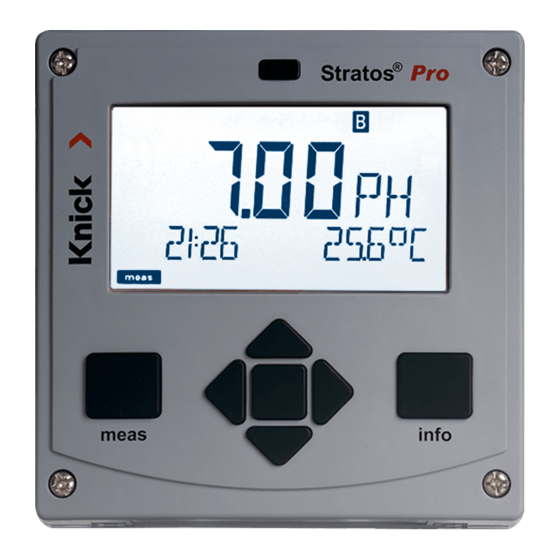
- Page 1 Stratos®Pro A401B CONDI User Manual Latest Product Information: www.knick.de 094711...
-
Page 2: Basics
Basics Copyright 2018 · Subject to change without notice. Return of products under warranty Please contact our Service Team before returning a defective device. Ship the cleaned device to the address you have been given. If the device has been in contact with process fluids, it must be de- contaminated/disinfected before shipment. -
Page 3: Documents Supplied
Documents Supplied Safety Instructions Quickstart Guides Installation and first steps: • Operation • Menu structure • Calibration • Error messages and recommended actions Specific Test Report Control Drawings Up-to date documentation available on our website: www.knick.de... -
Page 4: Table Of Contents
Basics ......................2 Documents Supplied ................3 Introduction ..................7 Intended Use ..................7 Safety Information ...............12 Overview of Stratos Pro A401B CONDI ........14 Assembly ..................15 Package Contents ................15 Mounting Plan, Dimensions ............16 Pipe Mounting, Protective Hood ..........17 Panel Mounting ..................18 Installation ..................19... - Page 5 Contents Operating Modes ................38 Menu Structure of Modes and Functions .........39 HOLD Mode ..................40 Alarm ......................41 Alarm and HOLD Messages ............42 Configuration ................44 Parameter Set A/B ................46 Configuration (Original for Copy) ..........52 Sensor .....................56 Current Output 1 ................62 Current Output 2 ................72 Temperature Compensation ............74 CONTROL Input ..................78 Alarm Settings ..................80...
- Page 6 Contents Specifications ................127 Calibration Solutions ..............135 Concentration Measurement ...........137 Concentration Curves ..............138 Error Handling ................144 Error Messages ................145 Sensoface ..................147 FDA 21 CFR Part 11 ..............149 Electronic Signature – Passcodes ..........149 Audit Trail ....................149 Index .....................150 Trademarks ..................159 Passcodes ..................160...
-
Page 7: Introduction
Introduction Intended Use Stratos Pro A401B CONDI is a 4-wire device for measurement of electrical conductivity and temperature in liquids using electrodeless (toroidal) sensors. Fields of application are: biotechnology, chemical industry, environment, food processing, water/wastewater treatment. Enclosure and mounting possibilities •... - Page 8 Introduction Display Plain-text messages in a large, backlit LC display allow intuitive operation. You can specify which values are to be displayed in standard measuring mode (“Main Display”, see page 36). Color-coded user interface The colored display backlighting signals different operating states (e.g.
- Page 9 Introduction Control inputs I input Current The analog (0) 4 ... 20 mA current input can be used for external temperature compen- input sation (TAN required). See page 76. HOLD HOLD (floating digital control input) The HOLD input can be used for external input activation of the HOLD mode, see page 41.
- Page 10 Introduction Signal outputs The device provides two current outputs (for transmission of measured value and temperature, for example). The output curve is adjustable (linear, bilinear or logarithmic), see page 62 onwards. Relay contacts Four floating relay contacts are available. Current outputs Output 1 The floating current outputs (0) 4 ... 20 mA are used for transmitting measured values.
- Page 11 Typical Application of Stratos Pro A401B CONDI...
-
Page 12: Safety Information
Safety Information Be sure to read and observe the following safety instructions! The device has been manufactured using state of the art technology and it complies with applicable safety regulations. When operating the device, certain conditions may nevertheless lead to danger for the operator or damage to the device. See also separate “Safety Instructions“... - Page 13 For orientation, please refer to NFPA 70 (NEC), ANSI/ISA-RP12.06.01. • When installing the device in a hazardous location, observe the specifications of the Control Drawing (download: www.knick.de). • Before commissioning, you must provide proof that the device may be connected with other equipment, such as a supply unit includ- ing cables and wires.
-
Page 14: Overview Of Stratos Pro A401B Condi
Overview Overview of Stratos Pro A401B CONDI CONDI Output 1 input Output 2 RS 485 Alarm Current input Wash HOLD input Power Control input... -
Page 15: Assembly
Assembly Package Contents Check the shipment for transport damage and completeness! The package should contain: • Front unit, rear unit, bag containing small parts • Specific test report • Documentation (cf p. 3) Fig.: Assembling the enclosure 1) Jumper (3 x) 6) Sealing insert (1 x) 2) Washer (1 x), for conduit 7) Rubber reducer (1 x) -
Page 16: Mounting Plan, Dimensions
Assembly Mounting Plan, Dimensions 1) Cable gland (3 x) 2) Knockouts for cable gland or ½” conduit, 21.5 mm dia. (2 knockouts) Conduits not included! 3) Knockout for pipe mounting (4 x) 4) Knockout for wall mounting (2 x) Fig.: Mounting plan (All dimensions in mm!) -
Page 17: Pipe Mounting, Protective Hood
Assembly Pipe Mounting, Protective Hood ø40...ø60 1) Hose clamp with worm gear drive to DIN 3017 (2 x) 2) Pipe-mount plate (1 x) 3) For vertical or horizontal posts or pipes 4) Self-tapping screw (4 x) Fig.: Pipe-mount kit, accessory ZU 0274 (All dimensions in mm!) Fig.: Protective hood for wall and pipe mounting, accessory ZU 0737 (All dimensions in mm!) -
Page 18: Panel Mounting
Assembly Panel Mounting < 30 1) Circumferential sealing (1 x) 2) Screws (4 x) 3) Position of control panel 4) Span piece (4 x) 5) Threaded sleeve (4 x) Cutout 138 x 138 mm (DIN 43700) 1...22 Fig.: Panel-mount kit, accessory ZU 0738 (All dimensions in mm!) -
Page 19: Installation
Installation Safety Precautions for Installation • Installation of the device must be carried out by trained experts in accordance with this user manual and as per applicable local and national codes. • Be sure to observe the technical specifications and input ratings during installation! •... -
Page 20: Rating Plates / Terminal Assignments
+55 °C Enclosure Type 4X 14163 Berlin Made in Germany Power: 00000 / 0000000 / 1845 Type A4**B-*/* 24 (-15%) to 230 (+10%) V AC, 45 to 65 Hz, < 12 VA APPROVED Installation 24 (-15%) to 80 (+10%) V DC , 4 W - 20 <... -
Page 21: Power Supply, Signal Lines
Power Supply, Signal Lines Connect the power supply for Stratos Pro A401B CONDI to terminals 21 and 22 (24 ... 230 V AC, 45 ... 65 Hz / 24 ... 80 V DC) Terminal assignments Areas for placing the screwdriver to pull out the terminals Fig.: Terminals, device opened, back of front unit... -
Page 22: Connecting The Sensor
Connecting the Sensor Connect the sensor lines with the sensor connection terminals (module terminals A...K). Sensor connection MK-CONDI module Areas for placing the screwdriver to pull out the terminals Fig.: MK-CONDI module terminal assignments Fig.: Terminals, device opened, back of front unit... -
Page 23: Cable Preparation Se 655 / Se 656
Cable Preparation SE 655 / SE 656 Preparing the shield connection Pre-assembled special cable for SE 655 / SE 656 sensors • Insert the special cable through the cable entry into the terminal compartment. • Remove the already separated part of the cable insulation (1). -
Page 24: Wiring Example: Se 655 / Se 656
Wiring Example: SE 655 / SE 656 Measuring task: Conductivity, temperature Sensors: SE 655/SE 656 sensor Connecting the pre-assembled cable... -
Page 25: Wiring Example: Se 660
Wiring Example: SE 660 Measuring task: Conductivity, temperature Sensor: SE 660 sensor... -
Page 26: Wiring Example: Yokogawa Isc 40
Wiring Example: Yokogawa ISC 40 Measuring task: Conductivity, temperature Sensor: Yokogawa ISC40 (Pt 1000) Jumper! Configuration settings for this sensor: Sensor: Conductivity, temperature SENSOR OTHER RTD TYPE 1000Pt CELL FACTOR 1.88 TRANS RATIO... -
Page 27: Wiring Example: Yokogawa Ic 40S
Wiring Example: Yokogawa IC 40S Measuring task: Conductivity, temperature Sensor: Yokogawa IC40S (NTC 30k) Configuration settings for this sensor: Sensor: Conductivity, temperature SENSOR RTD TYPE CELL FACTOR Approx. 1.7 TRANS RATIO... -
Page 28: Wiring Example: Se 670
Wiring Example: SE 670 Measuring task: Conductivity, temperature Sensor: SE 670 Cable types: M12/ferrules CA/M12-005NA 10 m CA/M12-010NA 20 m CA/M12-020NA The SE 670 sensor is connected to the RS-485 interface of the device – for an A2... Series (2-wire) device, the measuring module slot must be empty. -
Page 29: Connecting The Se 670 Sensor
Connecting the SE 670 Sensor NOTICE! The slot for the MK-CONDI module must be empty – be sure to remove the module! Areas for placing the screwdriver to pull out the terminals 13 14 Connection of SE 670: Wire color Brown Green Yellow... -
Page 30: Protective Wiring Of Relay Contacts
Protective Wiring of Relay Contacts Relay contacts are subject to electrical erosion. Especially with inductive and capacitive loads, the service life of the contacts will be reduced. For suppression of sparks and arcing, components such as RC combinations, nonlinear resistors, series resistors and diodes should be used. - Page 31 Protective Wiring of Relay Contacts Typical Protective Wiring Measures DC application with inductive load AC/DC applications with capacitive load Connection of incandescent lamps Inductive load Free-wheeling diode, e.g. 1N4007 (Observe polarity) Contact Capacitive load Resistor, e.g. 8 Ω / 1 W at 24 V / 0.3 A Contact Incandescent lamp, max 60 W / 230 V, 30 W / 115 V Contact...
-
Page 32: User Interface, Keypad
User Interface, Keypad MEMO SENS 1 IrDA transmitter/receiver 2 Display 3 Keypad 4 Rating plate (enclosure bottom) Function • Return to last menu level • Directly to measuring mode (press > 2 s) • Measuring mode: other display • Retrieve information •... -
Page 33: Display
Display MEMO SENS 1 Temperature 13 Info available 2 Sensocheck 14 Hold mode active 3 Interval/response time 15 Main display 4 Sensor data 16 Secondary display 5 Not used 17 Proceed using enter 6 Limit message: 18 Not used Limit 1 or Limit 2 19 Diagnostics 7 Alarm... -
Page 34: Measuring Mode
Measuring Mode After the operating voltage has been connected, the analyzer auto- matically goes to “Measuring“ mode. To call the measuring mode from another operating mode (e.g. Diagnostics, Service): Hold meas key depressed (> 2 s). Sensoface indicator Active (sensor status) parameter set (configuration) Time... -
Page 35: Selecting The Mode / Entering Values
Selecting the Mode / Entering Values To select the operating mode: 1) Hold meas key depressed (> 2 s) (directly to measuring mode) 2) Press menu key: the selection menu appears 3) Select operating mode using left / right arrow key 4) Press enter to confirm the selected mode Selection menu Selected mode... - Page 36 Display in Measuring Mode The MAIN DISPLAY is the display which is shown in measuring mode. To call the measuring mode from any other mode, hold the meas key depressed for at least 2 sec. meas key enter key meas By pressing meas briefly you can step through further displays such as tag number (TAG) or flow (L/h).
-
Page 37: Color-Coded User Interface
Color-Coded User Interface The color-coded user interface guarantees increased operating safety. Operating modes are clearly signaled. The normal measuring mode is white. Information text appears on a green screen and the diagnostic menu appears on turquoise. The orange HOLD mode (e.g. during calibration) is quickly visible as is the magenta screen which indicates asset management messages for predictive diagnostics –... -
Page 38: Operating Modes
Operating Modes Diagnostics Display of calibration data, display of sensor data, performing a device self-test, viewing the logbook entries, display of hardware/software ver- sions of the individual components. The logbook can store 100 events (00...99). They can be displayed directly on the device. The logbook can be extended to 200 entries using a TAN (Option). -
Page 39: Menu Structure Of Modes And Functions
Menu Structure of Modes and Functions Controller Meas. mode TAG display CLK display parameter display (main display selectable) (if configured) after 60 s after 60 s Pressing the menu key (down arrow) opens the selection menu. Select the menu group using the left/right arrow keys. Pressing enter opens a menu item. -
Page 40: Hold Mode
HOLD Mode The HOLD mode is a safety state during configuration and calibration. Output current is frozen (LAST) or set to a fixed value (FIX). Alarm and limit contacts are disabled. The HOLD mode is indicated by orange display backlighting. HOLD mode, display icon: Output signal response •... -
Page 41: Alarm
Alarm External activation of HOLD (SW-A005) The HOLD mode can be activated from outside by sending a signal to the HOLD input (e.g. from the process control system). Power supply HOLD 12...24 V AC/DC input Process control system HOLD inactive 0...2 V AC/DC HOLD active 10...30 V AC/DC... -
Page 42: Alarm And Hold Messages
Alarm and HOLD Messages Message Released by Cause Alarm Sensocheck Polarization / Cable (22 mA) Error Messages Flow (CONTROL input) Alarm ERR 10: Conductance > 3500 mS contact opens HOLD HOLD HOLD via menu or input (Last/Fix) CONF Configuration Calibration SERVICE Service... - Page 43 Alarm and HOLD Messages Generating a message via the CONTROL input (min. flow / max. flow) The CONTROL input can be used for parameter set selection or for flow measurement (pulse principle), depending on its assignment in the “Configuration” menu. When preset to flow measurement an alarm can be generated when the measured flow exceeds a specified range:...
-
Page 44: Configuration
Configuration The configuration steps are assigned to different menu groups. With the left/right arrow keys you can jump between the individual menu groups. Each menu group contains menu items for setting the parameters. Pressing enter opens a menu item. Use the arrow keys to edit a value. Press enter to confirm/save the settings. - Page 45 Configuration Parameter set A/B: configurable menu groups The device provides 2 parameter sets “A“ and “B“. By switching between the param- eter sets you can adapt the device to different measurement situations, for example. Parameter set “B“ only permits setting of process-related parameters. Menu group Parameter set A Parameter set B...
-
Page 46: Parameter Set A/B
Configuration Parameter Set A/B Manual Selection. Signaling via WASH Contact. Display Action Remark To switch between Manual selection of parameter sets must have parameter sets: been preset in CONFIG Press meas. mode. Default setting is a fixed parameter set A. Wrong settings change the measurement properties! - Page 47 Configuration Configuration Choices Default Sensor (SENSOR) SNS: SE 655 SE 655 SE 656 SE 660 SE 670 OTHER OTHER RTD TYPE 100PT / 1000PT / 1000PT 30 NTC CELL FACTOR XX.XXx 01.980 TRANS RATIO XXX.Xx 120.0 MEAS MODE Cond Cond Conc % Sal ‰...
- Page 48 Configuration Configuration Choices Default Output 1 (OUT1) OT1: RANGE 0–20 mA 4–20 mA 4–20 mA Channel Cond/TMP Cond Output (with Cond only) LIN / BiLIN / LOG BEGIN (0) 4mA xxxx 000.0 mS/cm END 20 mA xxxx 100.0 mS/cm BiLIN BEGIN (0) 4 mA END 20 mA CORNER X...
- Page 49 Configuration Configuration Choices Default Output 2 (OUT2) RANGE 0–20 mA / 4–20 mA 4–20 mA CHANNEL Cond/TMP ... other steps like output 1 Temperature compensation (CORRECTION) TC SELECT LIN, NLF, NaCl TC LIQUID 00.00 ...19.99%/K 00.00%/K REF TEMP 000.0 ... 199.9 °C 025.0 °C I-INPUT (only with TEMP EXT selected –...
- Page 50 Configuration Configuration Choices Default Switching outputs (Rel1/Rel2) Selected in text line CHANNEL FUNCTION CONTACT LEVEL Within meas. range HYSTERESIS 0 ... 50 % full scale DELAYTIME CHANNEL FUNCTION CONTACT LEVEL Within meas. range HYSTERESIS 0 ... 50 % full scale DELAYTIME CHANNEL TYPE...
- Page 51 Configuration Configuration Choices Default Cleaning contact (WASH) Selected in text line WASH WASH PARSET A/B WASH WASH CYCLE 000.0...999.9 h 000.0 h WASH TIME 0000...9999 SEC 0060 SEC CONTACT N/O, N/C Parameter set (PARSET) Select fixed parameter set (A) PARSET FIX / or switch between A/B via CNTR INPUT / (fixed parameter...
-
Page 52: Configuration (Original For Copy)
Configuration (Original for Copy) Two complete parameter sets are stored in the EEPROM. As delivered, the two sets are identical but can be edited. Note: Fill in your configuration data on the following pages or use them as original for copy. - Page 53 Configuration (Original for Copy) Parameter Parameter set A Parameter set B SNS: Sensor type SNS: RTD type SNS: Cell factor SNS: Transfer ratio SNS: Measuring mode SNS: Measuring range SNS: Concentration determination SNS: Temperature unit SNS: CIP counter SNS: SIP counter OT1: Current range OT1: Process variable OT1: Lin/bilin/log output...
- Page 54 (Original for Copy) Configuration Parameter Set A Set B OT2: Current range OT2: Process variable OT2: Lin/bilin/log output OT2: Current start OT2: Current end OT2: Vertex X (bilinear curve only) OT2: Vertex Y (bilinear curve only) OT2: Filter time OT2: 22 mA error current OT2: HOLD mode OT2: HOLD-FIX current COR: TC SELECT...
- Page 55 Configuration (Original for Copy) Parameter Set A Set B RL2: Process variable RL2: Function RL2: Contact response RL2: Setpoint RL2: Hysteresis RL2: Delay CTR: Process variable CTR: Controller type CTR: Pulse length CTR: Pulse frequency CTR: Setpoint CTR: Neutral zone CTR: P gain CTR: I time CTR: D time...
-
Page 56: Sensor
Configuration Sensor Select: Sensor type, temperature probe, cell factor, transfer ratio, measuring mode, range 1) Press menu key. 2) Select CONF using keys, press enter. 3) Select parameter set using , press enter. 4) Select SENSOR menu using keys, press enter. - Page 57 Configuration Menu item Action Choices Sensor type SE 655 Select sensor type using keys. SE 656 SE 660 SE 670 Press enter to confirm. OTHER Only with OTHER: 1000PT Temperature probe Select type of tempera- 100PT ture probe using 30 NTC keys.
- Page 58 Configuration Sensor Select: Concentration determination, temperature unit 1) Press menu key. 2) Select CONF using keys, press enter. 3) Select parameter set using , press enter. 4) Select SENSOR menu using keys, press enter. 5) All items of this menu group are indicated by the “SNS:”...
- Page 59 Configuration Menu item Action Choices Concentration For conc measurement -01- (NaCl) only -02- (HCl) determination -03- (NaOH) Select desired concentra- -04- (H tion solution using -05- (HNO (see appendix for ranges). -06- (H -07- (HCl) Press enter to confirm. -08- (HNO -09- (H -10- (NaOH)
- Page 60 Configuration Sensor (ISM only) Adjust: CIP cleaning cycles, SIP sterilization cycles 1) Press menu key. 2) Select CONF using keys, press enter. 3) Select parameter set using , press enter. 4) Select SENSOR menu using keys, press enter. 5) All items of this menu group are indicated by the “SNS:”...
- Page 61 Configuration Menu item Action Choices CIP / SIP (ISM only) The following adjustments are possible for ISM sensors: Cleaning cycles Select ON or OFF using ON/OFF keys. on/off Activates/deactivates log- ging in extended logbook Press enter to confirm. Sterilization cycles Select ON or OFF using ON/OFF ...
-
Page 62: Current Output 1
Configuration Current Output 1 Output current range. Linear/Logarithmic. Current start. 1) Press menu key. 2) Select CONF using keys, press enter. 3) Select parameter set using , press enter. 4) Select OUT1 menu using keys, press enter. 5) All items of this menu group are indicated by the “OT1:”... - Page 63 Configuration Menu item Action Remark Current range Select 4-20 mA or 0-20 mA range using keys. Press enter to confirm. Process variable Selectable decades with Select using keys: logarithmic setting (LOG): Cond: Conductivity TMP: Temperature Press enter to confirm. Then select characteristic (LIN/biLIN/LOG).
- Page 64 Configuration Current Output 1 Output current curve, bilinear 1) Press menu key. 2) Select CONF using keys, press enter. 3) Select parameter set using , press enter. 4) Select OUT1 menu using keys, press enter. 5) All items of this menu group are indicated by the “OT1:”...
- Page 65 Configuration Menu item Action Choices Output current Select using keys. Linear characteristic Press enter to confirm. curve biLIN Bilinear curve Logarithmic curve Current start Entered value applies to Enter value using selected process variable/ keys. and current end range If the adjusted range is exceeded, the device...
- Page 66 Logarithmic Curve Nonlinear output current characteristic: allows measurements over several decades, e.g. measuring very low values with a high resolution and high values with a low resolution. Parameters required: Start and end value Possible start and end values The start value must be at least one decade lower than the end value. Start value and end value must be specified in the same units (either in µS/cm or in S/m, see listing): 0.001 mS/cm...
- Page 67 Configuration Menu item Action Choices Logarithmic curve Select using keys. Logarithmic curve Press enter to confirm. of output current biLIN Bilinear curve Linear characteristic Start value Start value of logarithmic Enter value using output curve keys. Press enter to confirm. End value End value of logarithmic Enter value using ...
- Page 68 Configuration Current Output 1 Adjusting the time interval of the output filter 1) Press menu key. 2) Select CONF using keys, press enter. 3) Select parameter set using , press enter. 4) Select OUT1 menu using keys, press enter.
- Page 69 Configuration Menu item Action Choices Time averaging filter Enter value using keys. Press enter to confirm. Time averaging filter To smoothen the current output, a low-pass filter with adjustable filter time constant can be switched on. When there is a jump at the input (100 %), the output level is at 63 % after the time interval has been reached.
- Page 70 Configuration Current Output 1 Output current during Error and HOLD 1) Press menu key. 2) Select CONF using keys, press enter. 3) Select parameter set using , press enter. 4) Select OUT1 menu using keys, press enter. 5) All items of this menu group are indicated by the “OT1:”...
- Page 71 Configuration Menu item Action Choices Output current Select ON (22 mA for ON/OFF error message) or OFF during error message using keys. Press enter to confirm. Output current LAST/FIX LAST: During HOLD the last measured value is during HOLD maintained at the output.
-
Page 72: Current Output 2
Configuration Current Output 2 Output current range. Process variable . . . 1) Press menu key. 2) Select CONF using keys, press enter. 3) Select parameter set using , press enter. 4) Select OUT2 menu using keys, press enter. - Page 73 Configuration Menu item Action Choices Current range 4-20 mA / 0-20 mA Select 4-20 mA or 0-20 mA range using keys. Press enter to confirm. Process variable Cond/TMP Select using keys: Begin: 0 °C Cond: Conductivity End: 100°C TMP: Temperature Press enter to confirm.
-
Page 74: Temperature Compensation
Configuration Temperature Compensation Selecting the compensation method. TC process medium. 1) Press menu key. 2) Select CONF using keys, press enter. 3) Select parameter set using , press enter. 4) Select CORRECTION menu using keys, press enter. 5) All items of this menu group are indicated by the “COR:”... - Page 75 Configuration Menu item Action Choices Temperature Select desired compensa- tion using keys: compensation OFF: Temperature compensa- tion switched off LIN: Linear temperature com- pensation with entry of temperature coefficient nLF: Temperature compensa- tion for natural waters to EN 27888 NaCl: from 0 to 26 % by wt (0 ...
- Page 76 Configuration Temperature Compensation Current input for temp measurement. 1) Press menu key. 2) Select CONF using keys, press enter. 3) Select parameter set using , press enter. 4) Select CORRECTION menu using keys, press enter. 5) All items of this menu group are indicated by the “COR:”...
- Page 77 Configuration Menu item Action Choices With external temp measurement (current input enabled / TAN): Current range Select desired range using keys. Press enter to confirm. Current start Modify digit using Input range: keys, select next digit using keys. Press enter to confirm.
-
Page 78: Control Input
Configuration CONTROL Input Parameter set selection via external signal or flow measurement 1) Press menu key. 2) Select CONF using keys, press enter. 3) Select parameter set using , press enter. 4) Select CNTR_IN menu using keys, press enter. - Page 79 Configuration Menu item Action Choices Select function of PARSET Select using keys. (selecting parameter Press enter to confirm. CONTROL input set A/B via signal at CONTROL input) Flow (for connecting a pulse- output flow meter) Adjust to flow meter: With “Flow” selected, 12000 pulses/liter you must adjust the device to the flow meter...
-
Page 80: Alarm Settings
Configuration Alarm Settings Delay. Sensocheck. 1) Press menu key. 2) Select CONF using keys, press enter. 3) Select parameter set using , press enter. 4) Select ALARM menu using keys, press enter. 5) All items of this menu group are indicated by the “ALA:”... - Page 81 Configuration Menu item Action Choices Delay 0...600 SEC Enter value using (010 SEC) keys. Press enter to confirm. Sensocheck Select Sensocheck ON/OFF (continuous monitoring of sensor). Select ON or OFF using keys. Press enter to confirm (At the same time, Sensoface is activated.
- Page 82 Configuration Alarm Settings CONTROL input (FLOW MIN, FLOW MAX) 1) Press menu key. 2) Select CONF using keys, press enter. 3) Select parameter set using , press enter. 4) Select ALARM menu using keys, press enter. 5) All items of this menu group are indicated by the “ALA:”...
- Page 83 Configuration Menu item Action Choices CONTROL input The CONTROL input can generate an alarm when assigned to FLOW (flow monitoring) in the CONF menu: FLOW CNTR Flow measurement: allows monitoring the minimum and maximum flow (pulse counter) Alarm Specify value Default: 05.00 liters/h Minimum flow FLOW MIN...
-
Page 84: Limit Function
Configuration Limit Function Relay 1 1) Press menu key. 2) Select CONF using keys, press enter. 3) Select parameter set using , press enter. 4) Select REL1/REL2 menu using keys, press enter. 5) All items of this menu group are indicated by the “RL1:”... - Page 85 Configuration Menu item Action Choices Use of relays Select in the text line using keys: • Limit function (LIMITS) Note: Selecting • Controller (CONTROLLER) CONTROLLER leads to Controller menu group CTR. Press enter to confirm. Select process Select desired process variable using ...
- Page 86 Configuration Limit Function Relay 1 1) Press menu key. 2) Select CONF using keys, press enter. 3) Select parameter set using , press enter. 4) Select REL1/REL2 menu using keys, press enter. 5) All items of this menu group are indicated by the “RL1:”...
- Page 87 Configuration Menu item Action Choices Limit 1 hysteresis Select hysteresis using 0 ... 50 % full scale keys. Press enter to confirm. Limit 1 delay The contact is activated 0...9999 SEC (0010 SEC) with delay (deactivated without delay) Adjust delay using ...
- Page 88 Configuration Limit Function Relay 2 1) Press menu key. 2) Select CONF using keys, press enter. 3) Select parameter set using , press enter. 4) Select REL1/REL2 menu using keys, press enter. 5) All items of this menu group are indicated by the “RL2:”...
- Page 89 Configuration Menu item Action Choices Select process Select desired process variable using keys. variable Press enter to confirm. (CHANNEL) Limit 2 function Select desired function using keys. (FUNCTION) Press enter to confirm. Limit 2 icon: Limit 2 contact type N/O: normally open contact (CONTACT)
- Page 91 Controller Functions Typical Applications P controller Application for integrating control systems (e.g. closed tank, batch processes). PI controller Application for non-integrating control systems (e.g. drains). PID controller The additional derivative action compensates for measurement peaks. Controller characteristic +100 % Controller output Yp [%] Relay 1 Neutral zone Yp=0...
- Page 92 Controller Functions Controller equations Controller output Y = P action I action D action with: Proportional action Reset time [s] Proportional action Y Rate time [s] Controller gain [%] Setpoint - Meas. value Measuring range Neutral zone (Y=0) Tolerated deviation from desired value. With the setting “1 mS/cm”, for example, a deviation of ±...
-
Page 93: Pulse Length / Pulse Frequency Controller
Controller Functions Pulse Length / Pulse Frequency Controller Pulse length controller (PLC) The pulse length controller is used to operate a valve as an actuator. It switches the contact on for a time that depends on the controller output. The period (pulse length) is constant. A minimum ON time of 0.5 sec is maintained even if the controller output takes correspond- ing values (Y=0: Off ). -
Page 94: Controller
Configuration Controller (For description, see Controller Functions) Process variable. Controller type. Setpoint. 1) Press menu key. 2) Select CONF using keys, press enter. 3) Select parameter set using , press enter. 4) Select REL1/REL2 menu using keys, press enter. 5) All items of this menu group are indicated by the “CTR:”... - Page 95 Configuration Menu item Action Choices Use of relays LIMITS / CONTROLLER Select in the text line using keys: • CONTROLLER Selecting CONTROLLER leads to Controller menu Press enter to confirm. group CTR. Select process Cond/TMP Select desired process variable using keys. variable Press enter to confirm.
- Page 96 Configuration Controller (For description, see Controller Functions) Neutral zone. P, I, D actions. Behavior during HOLD 1) Press menu key. 2) Select CONF using keys, press enter. 3) Select parameter set using , press enter. 4) Select REL1/REL2 menu using keys, press enter.
- Page 97 Configuration Menu item Action Choices Neutral zone Adjust neutral zone using 0...50 % full scale keys. You can change the input range using the left/right arrow keys. Press enter to confirm. Controller: P action Adjust P action using 10...9999 % (0100 %) ...
-
Page 98: Wash Contact
Configuration WASH Contact Controlling a rinsing probe or signaling the parameter set 1) Press menu key. 2) Select CONF using keys, press enter. 3) Select parameter set A using keys, press enter. 4) Select WASH menu using keys, press enter. - Page 99 Configuration Menu item Action Choices Function Select WASH contact function using keys. WASH: Control of rinsing probes With PARSET A/B selected, the contact signals: “Parameter set A“ (open contact) “Parameter set B“ (closed contact) Press enter to confirm. Cleaning interval Only with WASH: Adjust value using ...
-
Page 100: Time And Date
Configuration Time and Date Tag Number 1) Press any arrow key. 2) Select CONF using keys, press enter. 3) Select parameter set A using keys, press enter. 4) Select CLOCK or TAG using keys, press enter. 5) All items of this menu group are indicated by the “CLK:”... - Page 101 Configuration Time and Date Control of the calibration and cleaning cycles is based on the time and date of the integrated real-time clock. In measuring mode the time is shown in the lower display. When using digital sensors, the calibration data is written in the sensor head.
-
Page 103: Calibration
Calibration NOTICE: • All calibration procedures must be performed by trained person- nel. Incorrectly set parameters may go unnoticed, but change the measuring properties. Calibration can be performed by: • Determining the cell factor with a known calibration solution taking account of the temperature •... -
Page 104: Calibration With Calibration Solution
Calibration Calibration with Calibration Solution Input of temperature-corrected value of calibration solution with simultaneous display of cell factor. Be sure to use known calibration solutions and the respective temper- ature-corrected conductivity values (see calibration solution tables in the appendix). During the calibration procedure the temperature must be kept constant. - Page 105 Calibration Display Action Remark The cell factor and zero point are displayed. The “hourglass” icon is blinking. Use the arrow keys to select: • Repeat (repeat calibration) or • Measuring. Press enter to confirm. With MEAS selected: Display of measured Exit calibration by variable, Sensoface pressing enter.
-
Page 106: Product Calibration
Calibration Product Calibration (Calibration by sampling) For product calibration, the uncompensated conductivity (mS/cm, S/m) is used. During product calibration the sensor remains in the process. The measurement process is only interrupted briefly. Procedure: 1) The sample is measured in the lab or directly on the site using a portable meter. - Page 107 Calibration Display Action Remark The device returns to From the blinking measuring mode. CAL mode indicator you see that product calibration has not been terminated. Product calibration Display (3 sec) step 2: Now the device is in When the sample value HOLD mode.
-
Page 108: Calibration By Input Of Cell Factor
Calibration Calibration by Input of Cell Factor You can directly enter the value for the cell factor of a sensor. This value must be known, e.g. determined beforehand in the laboratory. The selected process variable and the temperature are displayed. This method is suitable for all process variables. -
Page 109: Zero Calibration In Air / With Calibration Solution
Calibration Zero Calibration in Air / with Calibration Solution Display Action Remark Select Calibration. Press enter to proceed. Select CAL_ZERO calibration method. Press enter to proceed. Ready for calibration. Display (3 sec) Hourglass blinks. Now the device is in HOLD mode. Calibration in air. -
Page 110: Temp Probe Adjustment
Temp probe adjustment Calibration Temp Probe Adjustment Display Action Remark Select Calibration. Wrong settings Press enter to proceed. change the Select CAL_RTD measurement calibration method. properties! Press enter to proceed. Measure the tempera- Display (3 sec) ture of the process Now the device is in medium using an HOLD mode. -
Page 111: Measurement
Measurement Display Remark From the configuration or calibration menus, you can switch the device to measuring mode by pressing the meas key. In the measuring mode the main display shows the configured process variable (Cond or AM/PM and °F: or temperature), the secondary display shows the time and the second configured process variable (Cond or temperature). - Page 112 Measurement Display Remark With activated controller, you can also step through the following displays by pressing the meas key. When no key has been pressed for 60 sec, the device returns to the standard display. Upper display: Controller output Y Secondary display: Setpoint Depending on configuration setting: conductivity or temperature.
-
Page 114: Diagnostics
Diagnostics (DIAG) Diagnostics In the Diagnostics mode you can access the following menus without interrupting the measurement: CALDATA viewing the calibration data SENSOR viewing the sensor data SELFTEST starting a device self-test LOGBOOK viewing the logbook entries MONITOR displaying currently measured values VERSION displaying device type, software version, serial number Access to diagnostics can be protected with a passcode... - Page 115 Diagnostics Display Menu item Displaying the calibration data Select CALDATA using, press enter to confirm. Use thekeys to select the desired parameter from the bottom line of the display The selected parameter is shown in the main display. Press meas to return to measurement.
- Page 116 Diagnostics Display Menu item Device self-test (To abort, you can press meas.) 1) Display test: Display of all segments with changing background colors white/green/red. Press enter to proceed. 2) RAM test: Hourglass blinks, then display of --PASS- - or --FAIL-- Press enter to proceed.
- Page 117 Diagnostics Display Menu item Displaying the logbook entries Select LOGBOOK using, press enter to confirm. By using the keys, you can scroll backwards and forwards through the logbook (entries -00-...-99-), -00- being the last entry. If the display is set to date/time, you can search for a particular date using the ...
- Page 118 Diagnostics Display Menu item Version Here, you find the data you require for requesting a device-specific Option. Display of device type, software/hardware version, and serial number for all device components. Use the keys to switch between software and hardware version. Press enter to proceed to next device component.
-
Page 119: Service
Service (SERVICE) A Service In the Service mode you can access the following menus: MONITOR Displaying currently measured values OUT1 Testing current output 1 OUT2 Testing current output 2 RELAY Testing the function of the 4 relays CONTROL Testing the controller function IRDA Activating and communicating via the IrDA interface CODES... - Page 120 Service Display Menu item Displaying the currently measured values (sensor monitor) with HOLD mode activated: Select MONITOR using, press enter to confirm. Select variable in the bottom text line using. The selected parameter is shown in the main display. As the device is in HOLD mode, you can perform validations using simulators without influencing the signal outputs.
- Page 121 Service Display Menu item Controller test (manual specification of controller output): This function is used to start up control loops or check the actuators. For bumpless changeover to automatic operation (exiting this function), configure an I-action component (reset time). Controller characteristic The lower display shows the currently adjusted controller output Yp.
- Page 122 Service Display Menu item Assigning passcodes: In the “SERVICE - CODES“ menu you can assign pass- codes to DIAG, HOLD, CAL, CONF, and SERVICE modes (Service preset to 5555). When you have lost the Service passcode, you have to request an “Ambulance TAN“ from the manufac- turer specifying the serial number of your device.
-
Page 124: Operating States
Operating States Operating status Measuring Diag 60 s CAL_SOL Cal solution CAL_CELL Cell factor P_CAL Product cal S1 P_CAL Product cal S2 CAL RTD Temp adjustm. CONF ParSet A CONF ParSet B CONF Passcodes SERVICE MONITOR SERVICE OUT 1 SERVICE OUT 2 SERVICE RELAIS SERVICE... - Page 125 Operating States Operating status SERVICE 22 mA IRDA Cleaning fct HOLD input Explanation: as configured (Last/Fix or Last/Off ) active manual...
-
Page 126: Product Line And Accessories
Product Line and Accessories Order Code Stratos Pro A 4... Channel 1 Channel 2 Example 0 1 B - CONDI 4-wire / 20...254 V AC/DC B,C,E Communication Without (HART retrofittable via TAN) 0 Version number Version Approvals General Safety FM / CSA Zone 2 / Cl 1 Div 2 Meas. -
Page 127: Specifications
Specifications CONDI input Input for toroidal (electrodeless) conductivity sensors SE 655, SE 656, SE 660, SE 670 Effective ranges Conductivity 0.000 ... 1999 mS/cm Concentration 0.00 ... 100.0% by wt Salinity 0.0 ... 45.0 % (0 ... 35 °C / 32 ... 95 °F) Display ranges Conductivity 0.000 ... - Page 128 Specifications Sensor standardization Input of cell factor with simultaneous display of selected process variable and temperature Input of calibration solution conductivity with simultaneous display of cell factor Product calibration for conductivity Zero adjustment Temperature probe adjustment Permissible cell factor 00.100 ... 19.9999 cm Permissible transfer ratio 010.0 ...
- Page 129 Specifications I input (TAN) Current input 0/4 ... 20 mA / 50 Ω for external temperature signal Start/end of scale Configurable –50 ... +250 °C / –58 ... +482 °F Characteristic Linear Measurement error 1.3) < 1% current value + 0.1 mA HOLD input Galvanically separated (optocoupler) Function...
- Page 130 Specifications Output 2 0/4 ... 20 mA, max. 10 V, floating (galv. connected to output 1) Process variable * Conductivity, resistivity, concentration, salinity, or temperature Characteristic Linear, bilinear or logarithmic Overrange * 22 mA in the case of error messages Output filter * filter, time constant 0 ...
- Page 131 Specifications Limit values Rel1/Rel2 Rel1/Rel2 contacts, floating, but inter-connected Contact ratings < 250 V / < 3 A / < 750 VA < 30 V / < 3 A / < 90 W Contact response * N/C or N/O Response delay * 0000 ... 9999 s Setpoints * As desired within range Hysteresis *...
- Page 132 Specifications Keypad Keys: meas, menu, info, 4 cursor keys, enter HART communication HART version 6 Digital communication by FSK modulation of output current 1 Device identification, measured values, status and messages, parameter setting, calibration, records Conditions Output current ≥ 3.8 mA and load resistance ≥ 250 Ω IrDA interface Infrared interface for firmware update FDA 21 CFR Part 11...
- Page 133 Specifications Explosion protection Stratos Pro A401B Power supply 24 (–15%) ... 230 (+10%) V AC/DC < 12 VA, < 4 W AC: 45 ... 65 Hz Overvoltage category II, protection class II Nominal operating conditions Ambient temperature –20 ... +55 °C Transport/Storage temperature –30 ...
- Page 134 Specifications Enclosure Molded enclosure made of glass-reinforced PBT, PC Mounting Wall, pipe/post or panel mounting Color Gray, RAL 7001 Ingress protection IP 67, NEMA 4X Flammability UL 94 V-0 Dimensions 148 mm x 148 mm x 117 mm Control panel cutout 138 mm x 138 mm to DIN 43 700 Weight Approx.
-
Page 135: Calibration Solutions
Calibration Solutions Potassium Chloride Solutions (Conductivity in mS/cm) Temperature Concentration [˚C] 0.01 mol/l 0.1 mol/l 1 mol/l 0.776 7.15 65.41 0.896 8.22 74.14 1.020 9.33 83.19 1.147 10.48 92.52 1.173 10.72 94.41 1.199 10.95 96.31 1.225 11.19 98.22 1.251 11.43 100.14 1.278 11.67... - Page 136 Calibration Solutions Sodium Chloride Solutions (Conductivity in mS/cm) Temperature Concentration [˚C] 0.01 mol/l 0,1 mol/l Saturated 0.631 5.786 134.5 0.651 5.965 138.6 0.671 6.145 142.7 0.692 6.327 146.9 0.712 6.510 151.2 0.733 6.695 155.5 0.754 6.881 159.9 0.775 7.068 164.3 0.796 7.257 168.8...
-
Page 137: Concentration Measurement
Concentration Measurement Ranges Substance Concentration ranges NaCl 0-26wt% (0°C) 0-26wt% (100°C) -01- Configuration 0-18wt% (-20 °C) 22-39wt% (-20 °C) 0-18wt% (50 °C) 22-39wt% (50°C) -02- -07- Configuration NaOH 0-13wt% (0 °C) 15-50wt% (0 °C) 0-24wt% (100 °C) 35-50wt% (100 °C) -03- Configuration -10-... -
Page 138: Concentration Curves
Concentration Curves -01- Sodium chloride solution NaCl -01- c [wt%] Concentration measurement not possible in this range. Conductivity versus substance concentration and process temperature for sodium chloride solution (NaCl) - Page 139 Concentration Curves -02- Hydrochloric acid HCl -07- -07- -02- c [wt%] Concentration measurement not possible in this range. Conductivity versus substance concentration and process temperature for hydrochloric acid (HCl) Source: Haase/Sauermann/Dücker; Z. phys. Chem. New Edition, Vol. 47 (1965)
- Page 140 Concentration Curves -03- Sodium hydroxide solution NaOH -10- -10- -03- c [wt%] Concentration measurement not possible in this range. Conductivity versus substance concentration and process temperature for sodium hydroxide solution (NaOH)
- Page 141 Concentration Curves -04- Sulfuric acid H -06- -09- -06- -04- -09- c [wt%] Concentration measurement not possible in this range. Conductivity versus substance concentration and process temperature for sulfuric acid (H Source: Darling; Journal of Chemical and Engineering Data; Vol.9 No.3, July 1964...
- Page 142 Concentration Curves -05- Nitric acid HNO -08- -05- -08- c [wt%] Concentration measurement not possible in this range. Conductivity versus substance concentration and process temperature for nitric acid (HN0 Source: Haase/Sauermann/Dücker; Z. phys. Chem. New Edition, Vol. 47 (1965)
-
Page 144: Error Handling
Error Handling Alarm condition: • The display backlighting turns red • The alarm icon is displayed • The complete measured-value display blinks • “ERR xxx“ is displayed in the lower menu line Press the [info] key to view a short error text: •... -
Page 145: Error Messages
Error Messages Info text Problem (is displayed in case of Error Possible causes fault when the Info key is pressed) ERR 99 Error in factory settings DEVICE FAILURE EEPROM or RAM defective This error message only occurs in the case of a total defect. The device must be repaired and recalibrated at the factory. - Page 146 Error Messages Info text Problem (is displayed in case of Error Possible causes fault when the Info key is pressed) ERR 10 Measuring range of CONDUCTANCE TOO HIGH conductance exceeded > 3500 mS ERR 11 Display range violation CONDUCTIVITY RANGE Cond >...
-
Page 147: Sensoface
Sensoface (Sensocheck must have been activated during configuration.) The smiley in the display (Sensoface) alerts to sensor problems (defective sensor, defective cable, maintenance required). The permitted calibration ranges and the conditions for a friendly, neutral, or sad Sensoface are summarized in the following table. - Page 148 Sensoface Display Problem Status Sensor defect Wrong or defective sensor or excessive cable capacitance (see also error message Err 15). Temperature Temperature outside range for TC, conc, sal...
-
Page 149: Fda 21 Cfr Part 11
FDA 21 CFR Part 11 Conformity with FDA 21 CFR Part 11 In their directive “Title 21 Code of Federal Regulations, 21 CFR Part 11, Electronic Records; Electronic Signatures“ the US American health agency FDA (Food and Drug Administration) regulates the production and processing of electronic documents for pharmaceutical devel- opment and production. -
Page 150: Index
Index 21 mA-output signal in HOLD mode 71 22 mA-output signal in case of fault 71 Access codes 160 Setting 122 Accessories 126 Alarm 41 Alarm contact 81 CONTROL input 82 Sensocheck 81 Signaling 144 Alarm and HOLD messages 42 Alarm settings 80 Ambulance TAN 122 Application in hazardous locations 13... - Page 151 Index Compensation, TC 74 Concentration curves Hydrochloric acid HCl 139 Nitric acid HNO3 142 Sodium chloride solution NaCl 138 Sodium hydroxide solution NaOH 140 Sulfuric acid H2SO4 141 Concentration measurement 137 Ranges 137 Concentration solution, selection 58 Configuration Alarm 80 CIP/SIP cycles 60 CONTROL input 78 Controller 94...
- Page 152 Index Controller 91 Configuration 94 Controller equations 92 Controller functions 91 Controller test 121 Controller type 95 Manual specification of controller output 121 Neutral zone 97 Pulse frequency 95 Pulse length 95 Setpoint 95 Controller characteristic 91 Current output 2 72 Current start/end 63 Data logger Description 8...
- Page 153 Index EEPROM test 116 Electrical installation 19 Electronic Signature, explanation 149 Enclosure Components 15 Mounting plan 16 Mounting possibilities 7 Entering values 35 Error handling 144 Error messages 145 Explosion protection 133 Extended logbook 117 FDA 21 CFR Part 11 149 FIX, output signal in HOLD mode 40 FLASH test 116 FLOW 79...
- Page 154 Index LAST, output signal in HOLD mode 40 Limit 1 84 Limit 2 88 Logarithmic curve 66 Logbook 117 MAIN DISPLAY 36 Measured values, display 117 Measuring mode 34 Display 111 Selecting 57 Measuring point, TAG 101 Menu structure 39 Configuration 44 Message via CONTROL input 43 Module test 116...
- Page 155 Index Overview Device features 8 Terminal assignments 14 Typical application 11 Package contents 15 Documents 3 Panel mounting 18 Parameter errors 144 Parameter set A/B Configurable menu groups 45 Description 8 Display 111 External switchover 45 Individual configuration data 53 Manual selection 46 Selection via external signal 78 Signaling via WASH contact 46...
- Page 156 Index Quickstart guides 3 RAM test 116 Rating plates 20 Registered trademarks 159 Relay 1, configuration 84 Relay 2, configuration 88 Relay contacts Block diagram 10 Protective wiring 30 Relay test 120 Release of options 122 Reset to factory settings 122 Return of products under warranty 2 Safety information 12 Safety instructions 3...
- Page 157 Index Service 119 Controller test 121 Factory setting 122 IrDA communication 121 Passcodes 122 Relay test 120 Releasing options 122 Sensor monitor 120 Specifying current outputs 120 Service functions 38 Service passcode lost 122 Signal colors 33, 37 Signal lines 21 SIP sterilization cycles, configuration 60 Software version, display 118 Specifications 127...
- Page 158 Index Time averaging filter 69 Trademarks 159 Universal power supply 9 User interface 32 WASH contact Configuration 98 Signaling parameter set 46 Weather protector 17 Wiring Terminal assignments 21 Wiring examples SE 655 / SE 656 24 SE 660 25 SE 670 (via RS-485) 28 Yokogawa IC 40S 27 Yokogawa ISC 40 26...
-
Page 159: Trademarks
The following names are registered trademarks. For practical reasons they are shown without trademark symbol in this manual. Stratos® Sensocheck® Sensoface® Memosens® is a registered trademark of Endress+Hauser Conducta GmbH and Knick Elektronische Messgeräte GmbH & Co. KG. HART® is a registered trademark of the HART Communication Foundation. -
Page 160: Passcodes
Mode of operation Passcode Service (SERVICE) 5555 Diagnostics (DIAG) HOLD mode Calibration (CAL) Configuration (CONF) Knick Elektronische Messgeräte GmbH & Co. KG Beuckestraße 22 14163 Berlin Germany Phone: +49 30 80191-0 Fax: +49 30 80191-200 info@knick.de www.knick.de...
Need help?
Do you have a question about the Stratos Pro A401B CONDI and is the answer not in the manual?
Questions and answers