Table of Contents
Advertisement
Quick Links
Advertisement
Table of Contents

Related Manuals for AXIOMTEK P1157S-881


Summary of Contents for AXIOMTEK P1157S-881
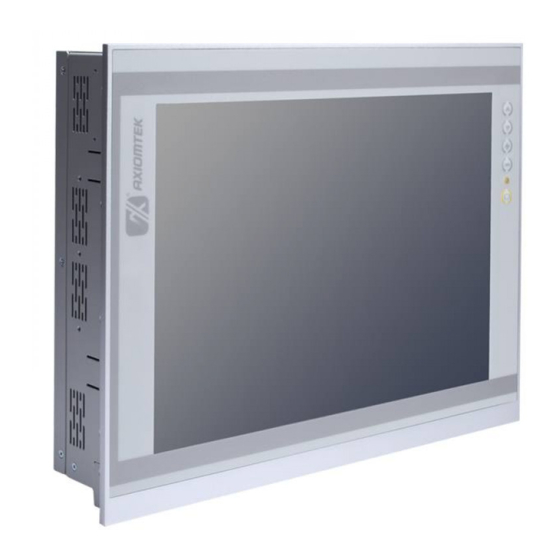
- Page 1 P1157S-881 All-in-One 15” XGA TFT Slim PANEL PC User’s Manual...
- Page 2 Axiomtek does not make any commitment to update the information in this manual. Axiomtek reserves the right to change or revise this document and/or product at any time without notice. No part of this document may be reproduced, stored in a retrieval system, or transmitted, in any form or by any means, electronic, mechanical, photocopying, recording, or otherwise, without the prior written permission of Axiomtek Co., Ltd.
-
Page 3: Safety Precautions
When handling boards and components, wear a wrist-grounding strap, available from most electronic component stores. Trademarks Acknowledgments Axiomtek is a trademark of Axiomtek Co., Ltd. ® Windows is a trademark of Microsoft Corporation. IBM, PC/AT, PS/2, VGA are trademarks of International Business Machines Corporation. -
Page 4: Table Of Contents
Table of Contents Disclaimers ..................... ii Safety Precautions ..................iii Chapter 1 Introduction ..........1 General Description ................1 Specifications ..................2 Dimensions and Outlines ..............4 I/O Outlets .................... 5 Packing List ..................6 Chapter 2 Hardware and Installation ...... 7 Open back cover ................. - Page 5 Chapter 4 Drivers Installation ......45 System ....................45 Touch Screen ..................45 Embedded O.S................... 48...
- Page 6 This page is intentionally left blank.
-
Page 7: Chapter 1 Introduction
Dimensions I/O Outlets Package List General Description ® The P1157S-881 adopts a 15-inch XGA TFT LCD with 250-nits brightness and Intel ® ® ® Core i7/i5/i3 series, Pentium and Celeron processors and Intel H81 chipset to provide excellent and powerful computing performance. -
Page 8: Specifications
P1157S-881 User’s Manual Powerful computing: Intel® 3rd Generation Core i7/i5/i3/Celeron processors ® ® ® 4th Core™ i7/i5/i3 series, Pentium P1157S-881 features Intel and Celeron processors and ® Intel H81 chipset which deliver high computing performance capability. Haswell CPU offers reliable and stable performance and rugged environment. - Page 9 P1157S-881 User’s Manual System Specification 15” XGA(1024 X 768)LCD 5 wired resistive Touch IP65/NEMA4 aluminum front bezel IP65 aluminum front bezel Net Weight 5.6 Kgs (12.35 lb) Dimension (Main Body Size) 378 x 72 x 309mm ...
-
Page 10: Dimensions And Outlines
P1157S-881 User’s Manual Dimensions and Outlines The following diagrams show the dimensions and outlines of P1157S-881. Introduction... -
Page 11: I/O Outlets
P1157S-881 User’s Manual I/O Outlets Please refer to the following illustration for I/O locations of the P1157S-881. Function 1 x RS-232/422/485 with 5V&12V (COM1) 1 x RS-232/422/485 with 5V&12V (COM2) 1 x RJ45 for GIGA Ethernet (LAN1) 1 x RJ45 for GIGA Ethernet (LAN2) 1 x RS-232 with 5V&12V (COM4) -
Page 12: Packing List
Panel mount kit x 6 Wall/VESA mount kit x 1 (optional) Rack mount kit x 1 (optional) Power cord x 1 If you can not find the package or any items are missing, please contact Axiomtek distributors immediately. Introduction... -
Page 13: Hardware And Installation
P1157S-881 User’s Manual Chapter 2 Hardware and Installation The P1157S-881 provides rich I/O ports and flexible expansions for you to meet different demand. The chapter will show you how to install the hardware. It includes: Open back cover ... -
Page 14: Open
P1157S-881 User’s Manual Open back cover This section tells users how to open back cover. Please follow the steps below. Step 1 Unscrew 3 screws on the back cover and push to the right side. Please refer the photo below. -
Page 15: Serial Ports Interface
P1157S-881 User’s Manual Serial Ports Interface This motherboard supports RS-232/422/485 on COM1~COM3 ports and 1 x RS-232 (COM4). The pin assignments are listed in table below. If you need to adjust these COM ports to work as RS-232/422/485, please refer to BIOS setting in section 5.4. -
Page 16: Ethernet
P1157S-881 User’s Manual Ethernet The P1157S-881 is equipped with two high performance plug and play Ethernet interfaces (RJ-45) which are fully compliant with the IEEE 802.3 standard. Connection can be established by plugging one end of the Ethernet cable into this RJ-45 connector and the other end to a 1000/100/10-Base-T hub. -
Page 17: Mountings: Panel / Wall / Rack / Desktop / Vesa
There are 5 application options for the P1157S-881, including Panel/Wall/Rack/ Desktop/VESA mounting ways. 2.4.1 VESA-ARM / Wall-Mount / Desktop-mount The P1157S-881 provides VESA mount: 75x75 mm or 100x100mm. Screw six screws to fix the kit in the back chassis. ▲... -
Page 18: Panel-Mount Kit Assembly
Fixing the bracket by six screws on the left and right side. 2.4.2 Panel-mount Kit Assembly The P1157S-881 is designed for panel mount application. To mount the P1157S-881, the standard set of mounting kit (included in the system packaging) is needed. -
Page 19: Rack-Mount Kit Assembly
P1157S-881 User’s Manual 2.4.3 Rack-mount Kit Assembly The P1157S-881 is designed for rack mount application. To mount the P1177S-871, the standard set of mounting kit (included in the system packaging) is needed. Step 1 Unscrew the fix screws from the left and right side of the system. -
Page 20: Hdd Installation
P1157S-881 User’s Manual HDD Installation The P1157S-881 provides a convenient Hard Disk Drive (HDD) bracket for users to install 2 x 2.5” or 1 x 3.5” SATA HDD. Please follow the steps: Step 1 Refer section 2.1 to open the back cover. - Page 21 P1157S-881 User’s Manual Step 4 Fix the HDD bracket into the main base. Step 5 Plug the power and SATA cables to connectors. Installation completes. AMI BIOS Setup Utility...
-
Page 22: Dram Installation
P1157S-881 User’s Manual DRAM Installation The P1157S-881 provides two 204-pin DDR3 SO-DIMM socket that support system memory up to 16GB. Please follow steps below to install the memory modules: Step 1 Refer to section 2.1 to open the back cover and find out DIMM socket on mainboard (MANO871). - Page 23 P1157S-881 User’s Manual Step 3 Install the SO-DIMM module into the slot and press it firmly down until it seats correctly. Step 4 The slot latches are levered upwards and latch on to the edges of the SO-DIMM. AMI BIOS Setup Utility...
-
Page 24: Cpu Installation
P1157S-881 User’s Manual CPU Installation ® Core™ i7/i5/i3 series, The P1157S-881 has an LGA1155 socket supporting Intel &2 ® ® Pentium and Celeron processors and provides high computing performance for users. Step 1 Press the hook of lever down with your thumb and pull it to the right side to release it from retention tab. - Page 25 P1157S-881 User’s Manual Step 3 CPU aims at the socket and places the package carefully into the socket by purely vertical motion. NOTE Never touch fragile socket contacts to avoid damage and do not touch processor sensitive contacts at any time during installation.
-
Page 26: Cpu Cooler Installation
P1157S-881 User’s Manual CPU Cooler Installation Step 1 Making sure your CPU settled correctly on the socket. Step 2 Screw the cooling fan supporting base onto the CPU socket on the Motherboard and make sure the CPU fan is plugged to the CPU fan connector. -
Page 27: Wireless Lan Module Installation (Optional)
P1157S-881 User’s Manual Wireless LAN Module Installation (optional) The P1157S-881 provides one wireless LAN module to install. When installing the wireless LAN module, refer to the following instructions and illustration: Step 1 Refer to section 2.1 to open the back cover and find out the wireless LAN module located. - Page 28 P1157S-881 User’s Manual Step 3 Plug in USB cable to the connector of WIFI module. And, find the built-in Antenna cable and connect it wireless LAN card. Step 4 Lift the rubber stopper from the top of back cover. Step 5 Install the antenna on the antenna connector.
-
Page 29: Fan Tunnel Installation
P1157S-881 User’s Manual 2.10 Fan Tunnel Installation The P1157S-881 provides one fan tunnel to install. When installing the fan tunnel, refer to the following instructions and illustration: Step1 Spread the fan tunnel out flat. Step2 Tear the releasing paper from the dual face tape. - Page 30 P1157S-881 User’s Manual Step5 Let fan cable through the fan tunnel and stick to the cooler. AMI BIOS Setup Utility...
-
Page 31: Ami Bios Setup Utility
P1157S-881 User’s Manual Chapter 3 AMI BIOS Setup Utility The AMI UEFI BIOS provides users with a built-in setup program to modify basic system configuration. All configured parameters are stored in a flash chip to save the setup information whenever the power is turned off. This chapter provides users with detailed description about how to set up basic system configuration through the AMI BIOS setup utility. -
Page 32: Menu Bar
P1157S-881 User’s Manual Menu Bar The top of the screen has a menu bar with the following selections: Menu Bar Description Main To set up the system time/date information. Advanced To set up the advanced BIOS features. H/W Monitor To display current hardware status. -
Page 33: Main Menu
P1157S-881 User’s Manual Main Menu When you first enter the setup utility, you will enter the Main setup screen. You can always return to the Main setup screen by selecting the Main tab. System Time/Date can be set up as described below. -
Page 34: Advanced Menu
P1157S-881 User’s Manual Advanced Menu The Advanced menu also allows users to set configuration of the CPU and other system devices. You can select any of the items in the left frame of the screen to go to the sub menus: ►... - Page 35 P1157S-881 User’s Manual Instant Flash Instant Flash is a UEFI flash utility embedded in Flash ROM. This convenient UEFI update tool allows you to update system UEFI without entering operating systems first like MS-DOS or ® Windows . Just launch this tool and save the new UEFI file to your USB flash drive, floppy disk or hard drive, then you can update your UEFI only in a few clicks without preparing an additional floppy diskette or other complicated flash utility.
- Page 36 P1157S-881 User’s Manual CPU Configuration Active Processor Cores Select the number of cores to enable in each processor package. CPU C States Support Enable CPU C States Support for power saving. It is recommended to keep C3, C6 and C7 all enabled for better power saving.
- Page 37 P1157S-881 User’s Manual Intel SpeedStep Technology ® ® ’s new power saving technology. Processors can switch Intel SpeedStep technology is Intel between multiple frequencies and voltage points to enable power saving. The default value is ® Enabled. Configuration options are Enabled and Disabled. If you install Windows 7 / 8 and want to enable this function, please set this item to [Enabled].
- Page 38 P1157S-881 User’s Manual Chipset Configuration DRAM Frequency If Auto is selected, the motherboard will detect the memory module(s) inserted and assign the appropriate frequency automatically. Primary Graphics Adapter This allows you to select Onboard or PCI Express as the boot graphic adapter priority. The default value is PCI Express.
- Page 39 P1157S-881 User’s Manual Render Standby Use this to enable or disable Render Standby by Internal Graphics Device. The default value is Enabled. Onboard HD Audio Select Auto, Enabled or Disabled for the onboard HD Audio feature. If you select Auto, the onboard HD Audio will be disabled when PCI Sound Card is plugged.
- Page 40 P1157S-881 User’s Manual Storage Configuration SATA Controller(s) Use this item to enable or disable the SATA Controller feature. SATA Mode Selection Use this to select SATA mode. Configuration options are IDE Mode, AHCI Mode and RAID Mode. The default value is AHCI Mode.
- Page 41 P1157S-881 User’s Manual Intel(R) Smart Connect Technology Intel(R) Smart Connect Technology Use this item to enable or disable Intel(R) Smart Connect Technology. Intel(R) Smart Connect Technology keeps your e-mail and social networks, such as Twitter, Facebook, etc. updated automatically while the computer is in sleep mode. The default is Enabled.
- Page 42 P1157S-881 User’s Manual Super IO Configuration COM1 Configuration Use this to set parameters of COM1. COM1 port type options are RS232, RS422 or RS485. COM2 Configuration Use this to set parameters of COM2. COM2 port type options are RS232, RS422 or RS485.
- Page 43 P1157S-881 User’s Manual ACPI Configuration Suspend to RAM Use this item to select whether to auto-detect or disable the Suspend-to-RAM feature. Select Auto will enable this feature if the OS supports it. Check Ready Bit Use this item to enable or disable the feature Check Ready Bit.
- Page 44 P1157S-881 User’s Manual USB Mouse Power On Use this item to enable or disable USB Mouse to power on the system. USB Configuration USB Controller Use this item to enable or disable the use of USB controller. Intel USB 3.0 Mode ®...
- Page 45 P1157S-881 User’s Manual Voltage Configuration DRAM Voltage Use this to select DRAM Voltage. The default value is 1.50V. AMI BIOS Setup Utility...
-
Page 46: H/W Monitor Menu
P1157S-881 User’s Manual H/W Monitor Menu In this section, it allows you to monitor the status of the hardware on your system, including the parameters of the CPU temperature, motherboard temperature, CPU fan speed, chassis fan speed, and the critical voltage. -
Page 47: Boot Menu
P1157S-881 User’s Manual Boot Menu In this section, it will display the available devices on your system for you to configure the boot settings and the boot priority. Boot From Onboard LAN Use this item to enable or disable the Boot From Onboard LAN feature. - Page 48 P1157S-881 User’s Manual Enable to launch the Compatibility Support Module. Please do not disable unless you’re ® running a WHCK test. If you are using Windows 8 64-bit and all of your devices support UEFI, you may also disable CSM for faster boot speed.
-
Page 49: Security Menu
P1157S-881 User’s Manual Security Menu In this section, you may set, change or clear the supervisor/user password for the system. Secure Boot Use this to enable or disable Secure Boot. The default value is Disabled. AMI BIOS Setup Utility... -
Page 50: Exit Menu
P1157S-881 User’s Manual Exit Menu Save Changes and Exit When you select this option, it will pop-out the following message, “Save configuration changes and exit setup?”. Select OK to save the changes and exit the UEFI setup utility. Discard Changes and Exit When you select this option, it will pop-out the following message, “Discard changes and exit... - Page 51 P1157S-881 User’s Manual Chapter 4 Drivers Installation System P1157S-881 supports Windows 7 and WES 7. To facilitate the installation of system driver, please carefully read the instructions in this chapter before start installing. Insert Driver CD and select the “\Drivers”. Step 1 Step 2 Select all files and follow the installing procedure.
- Page 52 Driver Installation- Windows 7 The P1157S-881 provides a touch screen driver that users can install it under the operating system Windows 7. To facilitate installation of the touch screen driver, you should read the instructions in this chapter carefully before you attempt installation.
- Page 53 P1157S-881 User’s Manual Select the “Standard Calibrate” tab. Step 4 Step 5 Calibrations: To adjust the display with touch panel, click “Calibration” and follow the calibrate point to do calibration; there are five points on screen for calibration. Step 6 Press OK.
- Page 54 P1157S-881 User’s Manual Embedded O.S. The P1157S-881 provides the Windows 7 Embedded. The O.S. is supported devices which are listed below. WES 7 Here are supported onboard devices: Onboard Multi I/O SATA HDD PS2 Keyboard and mouse ...
Need help?
Do you have a question about the P1157S-881 and is the answer not in the manual?
Questions and answers