Table of Contents
Advertisement
Quick Links
Advertisement
Table of Contents

Related Manuals for AXIOMTEK P1127E-500


Summary of Contents for AXIOMTEK P1127E-500
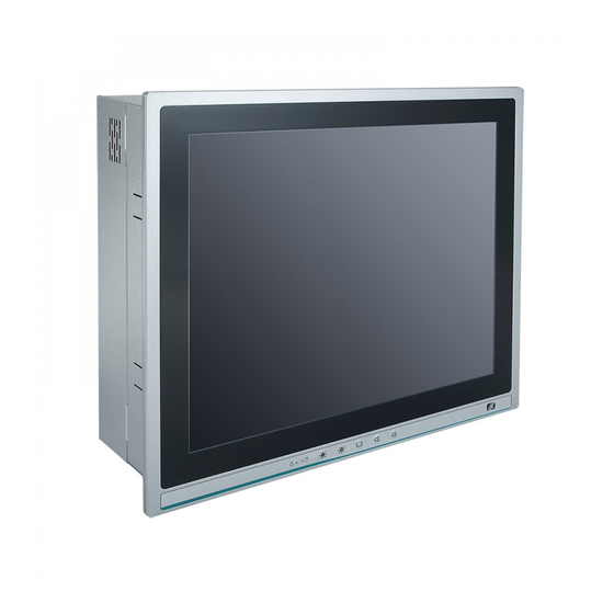
- Page 1 P1127E-500 All-in-One 12.1” XGA TFT Expandable Panel PC User’s Manual...
-
Page 2: Disclaimers
Disclaimers This manual has been carefully checked and believed to contain accurate information. Axiomtek Co., Ltd. assumes no responsibility for any infringements of patents or rights of any third party, or any liability arising from such use. Axiomtek does not warrant or assume any legal liability or responsibility for the accuracy, completeness or usefulness of any information in this document. -
Page 3: Safety Precautions
When handling boards and components, wear a grounding wrist strap available from most electronic component stores. Trademark Acknowledgments Axiomtek is a trademark of Axiomtek Co., Ltd. ® Windows is a trademark of Microsoft Corporation. IBM, PC/AT, PS/2, VGA are trademarks of International Business Machines Corporation. -
Page 4: Table Of Contents
Table of Contents Disclaimers ..................... ii Safety Precautions ..................iii Section 1 Introduction ..........1 General Description ................1 1.2.1 System Specifications ..................2 1.2.2 Mechanical/Environmental Specifications ............3 Dimensions and Outlines ..............4 I/O Outlets .................... 6 Section 2 Hardware and Installation ...... - Page 5 2.11.10 Fan Connectors (CPU_FAN1 and SYS_FAN1) ..........33 2.11.11 SIM Card Slot (SIM1) ..................34 2.11.12 SATA 3.0 Connectors (SATA1~SATA3) ............34 Section 3 AMI BIOS Setup Utility ......35 Starting ....................35 Navigation Keys ................35 Main Menu ..................36 Advanced Menu .................
- Page 6 This page is intentionally left blank.
-
Page 7: Introduction
P1127E-500 especially suitable for most rugged industrial environments. Expandable for PCIe (or PCI optional) The P1127E-500 comes with one PCIe x4 (or optionally one PCI) for expansion purposes. Users can easily plug in a standard half-size PCI or PCIe card as required. -
Page 8: System Specifications
Core™ Processors High Performance computing: 7th and 6th Generation Intel The P1127E-500 is powered by LGA1151 Socket 7th and 6th Generation Intel® Core™ i7/i5/i3, Pentium® and Celeron® processors which provide powerful performance and less power consumption. The latest Intel® Kaby Lake-S platform offers reliable and stable performance suitable for rugged environments. -
Page 9: Mechanical/Environmental Specifications
P1127E-500 User’s Manual Storage 1 x 2.5” SATA HDD Power connector 1 x AC plug 1.2.2 Mechanical/Environmental Specifications 12.1” XGA LCD (with resolutions 1024x768) 5 wired resistive touch IP65/NEMA4 aluminum front bezel ... -
Page 10: Dimensions And Outlines
P1127E-500 User’s Manual Dimensions and Outlines Diagram 1-1 and 1-2 show the outlines and dimensions of the P1127E-500, respectively. Diagram 1-1 Outlines of the P1127E-500 Introduction... - Page 11 P1127E-500 User’s Manual Diagram 1-2 Outlines of the P1127E-500 Introduction...
-
Page 12: I/O Outlets
P1127E-500 User’s Manual I/O Outlets Figure 1-2, 1-3 and Table 1-1, 1-2 illustrate the I/O locations of the P1127E-500 and their functions. Figure 1-2 Front view of the P1127E-500 Table 1-1 Functions of the front panel of the P1127E-500 Function... - Page 13 P1127E-500 User’s Manual Figure 1-3 Side view of the P1127E-500 Table 1-2 Functions of the I/O Outlets of the P1127E-500 Function 1 x Line-out 2 x USB2.0 2 x RJ45 for Gigabit Ethernet 1 x RS-232 (COM3) 1 x RS-232 (COM4)
- Page 14 P1127E-500 User’s Manual This page is intentionally left blank. Introduction...
-
Page 15: Hardware And Installation
P1127E-500 User’s Manual Section 2 Hardware and Installation The P1127E-500 provides rich I/O ports and flexible expansion to meet different demands. The section explains how to install the hardware. Packing List System Layout Mountings: Panel / Wall / Rack / Desktop / VESA ... -
Page 16: Packing List
If any above-mentioned item is missing, please contact an Axiomtek distributor immediately. System Layout To open the P1127E-500, simply unscrew the four screws on the back cover as shown in Figure 2-1, and then push the cover to the right side. - Page 17 P1127E-500 User’s Manual Once the back cover is removed, the internal system should look like Figure 2-2. Figure 2-2 After Removing the back cover of the P1127E-500, install memory, storage and any other peripherals. Hardware and Installation...
-
Page 18: Mountings: Panel / Wall / Rack / Desktop / Vesa
There are 5 application options for the P1127E-500, including Panel/Wall/Rack/ Desktop/VESA mounting ways. 2.3.1 VESA-ARM / Wall-Mount / Desktop-mount The P1127E-500 provides VESA mount: 75x75 mm or 100x100mm. Screw six screws to fix the kit in the back chassis. ▲ Bracket for VESA/wall/desktop mount ▲... -
Page 19: Panel-Mount Kit Assembly
Fixing the bracket by screwing the six screws on the left and right sides. 2.3.2 Panel-mount Kit Assembly The P1127E-500 is designed for panel mount application. To mount the P1127E-500, the standard set of the mounting kit (6 pieces included in the system packaging) is needed. Hardware and Installation... -
Page 20: Hdd Installation
P1127E-500 User’s Manual HDD Installation The P1127E-500 provides a convenient hard disk drive (HDD) bracket for users to install 1 x 2.5” SATA HDD. Please follow the steps: Step 1 Refer section 2.1 to open the back cover. Step 2 unplug the power cable and unscrew the 4 screws to take off the HDD bracket. - Page 21 P1127E-500 User’s Manual Step 4 Plug the power and SATA cables to the connectors. Step 5 Fix the HDD bracket into the main base. Installation is completed. Hardware and Installation...
-
Page 22: Dram Installation
P1127E-500 User’s Manual DRAM Installation The P1127E-500 provides one 288-pin DDR4 Long-DIMM socket that supports system memory up to 32GB. Please follow the steps below to install the memory modules. Step 1 Refer to section 2.1 to open the back cover and locate the DIMM socket on mainboard (MANO500). -
Page 23: Wireless Lan Module Installation (Optional)
P1127E-500 User’s Manual Wireless LAN Module Installation (optional) The P1127E-500 provides one wireless LAN module to install. When installing the wireless LAN module, refer to the following instructions and illustrations: Step 1 Refer to section 2.1 to open the back cover and locate the PCIe Mini-Card slot. - Page 24 P1127E-500 User’s Manual Step 3 Find the built-in antenna cable and connect it to the wireless LAN module. Step 4 Lift the rubber stopper from the top of the back cover. Step 5 Install the antenna on the antenna connector.
-
Page 25: Add-On Card Installation
P1127E-500 User’s Manual Add-on Card Installation The P1127E-500 provides a riser card (PCIe interface) for 1 x PCIe or 1 x PCI slots expansion. The riser card assembly can accommodate both half-size expansion cards. To install the riser card, refer to the following figures and instructions. - Page 26 P1127E-500 User’s Manual Step 3 Secure the metal bracket of the card to the system case with two screws. Installation is completed. NOTE: Please use a standard-sized add-on card to avoid conflict to the mechanism. Hardware and Installation...
-
Page 27: Board Layout
P1127E-500 User’s Manual Board Layout Hardware and Installation... -
Page 28: Rear I/O
P1127E-500 User’s Manual Rear I/O Table 2-1 Jumpers/Headers/Connectors associated with each Label Jumpers/Headers/Connectors Label Function Label Function Clear CMOS Jumper (JP1) PCI-Express x16 Slot (CN1) COM3~COM4 Headers (COM3~COM4) SATA 3.0 Connectors (SATA1~SATA3) AT/ATX Power Mode Select Jumper CPU Socket (JP2) USB 2.0 Wafers (CN13, CN14) -
Page 29: Jumper Settings
Diagram 2-1 illustrates how to set up a jumper. Diagram 2-1 Definitions of Pin Settings Before applying power to the P1127E-500 series, please make sure all of the jumpers are in default positions which are defined as follows: NOTE: In case that default jumper settings need to be changed, please make any change under the power-off condition. -
Page 30: Clear Cmos Select (Jp1)
P1127E-500 User’s Manual 2.10.1 Clear CMOS Select (JP1) JP1 is used to clear the Real Time Clock (RTC) RAM in CMOS. Data, time and system setup parameters stored in the CMOS memory can be cleared by erasing the CMOS RTC RAM data. -
Page 31: Com1 Data/Power Select (Jp6)
P1127E-500 User’s Manual 2.10.4 COM1 Data/Power Select (JP6) The COM1 port has the +5V power capability on DCD and +12V on RI by setting this jumper (3x2-pin p=2.54mm). Table 2-6 Jumper Settings for JP6 Function Setting Power: Set COM1 Pin 1 to +5V... -
Page 32: Connectors
P1127E-500 User’s Manual 2.11 Connectors Signals go to other parts of the system through connectors. Loose or improper connection may cause problems or malfunctions, Ensure that all connectors are properly and firmly connected. Table 2-7 is a summary listing the connectors on the hardware. -
Page 33: Audio Jack (Cn2)
P1127E-500 User’s Manual 2.11.1 Audio Jack (CN2) The motherboard provides an HD audio jack on the rear I/O. Install the audio driver, and then attach audio devices to CN2. Table 2-8 Color assignment for CN2 Pin Color Signal Green Line-out... -
Page 34: Displayport Connector (Cn5)
P1127E-500 User’s Manual 2.11.3 DisplayPort Connector (CN5) The DisplayPort interface is available through CN5. Table 2-11 Pin Assignment for CN5 Signal DP_TX0_P DP_TX0_N DP_TX1_P DP_TX1_N DP_TX2_P DP_TX2_N DP_TX3_P DP_TX3_N DP_AUXP DP_AUXN DP_HPD +3.3V 2.11.4 VGA Connector (CN6) The CN6 is a high-rise 15-pin D-Sub connector which is commonly used for VGA display. This... -
Page 35: Com Connector (Cn7)
P1127E-500 User’s Manual 2.11.5 COM Connector (CN7) The CN7 is a double-deck DB-9 connector for interfaces of COM1 and COM2 serial ports where only COM1 is selectable for RS-232/422/485 mode by jumper settings (see Section 2.3.3). The pin assignments of RS-232/422/485 are listed in Table 2-13 below. -
Page 36: Hdmi Connector (Cn8)
P1127E-500 User’s Manual 2.11.6 HDMI Connector (CN8) The HDMI (High-Definition Multimedia Interface) is a compact digital interface which is capable of transmitting high-definition video and high-resolution audio over a single cable. Table 2-15 Pin assignment for CN8 Signal Signal HDMI OUT_DATA2+... -
Page 37: Pci-Express Mini Card Connector (Cn11)
P1127E-500 User’s Manual 2.11.7 PCI-Express Mini Card Connector (CN11) The CN11 connector complies with the specifications V 1.2 of the PCI-Express Mini Card. Table 2-16 Pin assignment for CN11 Signal Pin Signal WAKE# +3.3VAUX +1.5V +3.3VAUX UIM_PWR UIM_DAT REFCLK- UIM_CLK... -
Page 38: Usb 2.0 Wafers (Cn13 And Cn14)
P1127E-500 User’s Manual 2.11.8 USB 2.0 Wafers (CN13 and CN14) CN13 and CN14 are 5x2-pin p=2.00mm headers for the USB 2.0 interface Table 2-17 Pin assignment for CN13 CN13 Signal CN13 Signal USB5- USB6- USB5+ USB6+ Table 2-18 Pin assignment for CN14... -
Page 39: Fan Connectors (Cpu_Fan1 And Sys_Fan1)
P1127E-500 User’s Manual 2.11.10 Fan Connectors (CPU_FAN1 and SYS_FAN1) This motherboard comes with two fan connectors. Fan speed option(s) can be found at BIOS Setup Utility through the path: Advanced\HW Monitor\PC Health Status. The CPU_FAN1 is a 4x1-pin p=2.54mm connector... -
Page 40: Sim Card Slot (Sim1)
P1127E-500 User’s Manual 2.11.11 SIM Card Slot (SIM1) The SIM1 is used when a SIM card is inserted. It is mainly used in 3G wireless network application. In order to work properly, the SIM card must be used together with a 3G module... -
Page 41: Ami Bios Setup Utility
P1127E-500 User’s Manual Section 3 AMI BIOS Setup Utility The AMI UEFI BIOS provides users with a built-in setup program to modify basic system configuration. All configured parameters are stored in a flash chip to save the setup information whenever the power is turned off. This Section provides users with detailed descriptions about how to set up basic system configuration through the AMI BIOS setup utility. -
Page 42: Main Menu
P1127E-500 User’s Manual Main Menu When you first enter the setup utility, you will enter the Main BIOS setup screen as shown below. You can always return to the Main setup screen by selecting the Main tab. System Time/Date can be set up as described below. -
Page 43: Advanced Menu
P1127E-500 User’s Manual Advanced Menu The Advanced menu allows users to set configurations of the CPU and other system devices. Select any of the items in the left frame of the screen to go to the sub menus: ► ACPI Settings ►... - Page 44 P1127E-500 User’s Manual IT8786 Super IO Configuration You can use this screen to select options for the Super IO Configuration, and change the value of the selected option. A description of the selected item appears on the right side of the screen. For items marked with “►”, please press <Enter>...
- Page 45 P1127E-500 User’s Manual Hardware Monitor This screen monitors hardware health status. This screen displays the temperatures of the system and CPU, cooling fans speed in RPM and system voltages (VCC_CPU, VIN1~VIN4 and VBAT). AMI BIOS Setup Utility...
- Page 46 P1127E-500 User’s Manual Smart Fan Function This screen allows you to select a CPU fan mode. CPU FAN Mode This item allows you to select a CPU fan mode, which can be set to Full On, Autom atic Mode and Manual Mode.
- Page 47 P1127E-500 User’s Manual Utility Configuration BIOS Flash Utility This is the screen of BIOS flash utility configuration. For more detailed information, please refer to Appendix B. AMI BIOS Setup Utility...
- Page 48 P1127E-500 User’s Manual ACPI Settings ACPI Sleep State When the suspend button is pressed, the ACPI (Advanced Configuration and Power Interface) sleep state is S3 (Suspend to RAM). AMI BIOS Setup Utility...
- Page 49 P1127E-500 User’s Manual CPU Configuration This screen shows the CPU information, and you can change the value of the selected option. Intel Virtualization Technology Enable or disable Intel Virtualization Technology. When enabled, a VMM (Virtual Machine Mode) can utilize the additional hardware capabilities. It allows a platform to run multiple operating systems and applications independently, hence enabling a single computer system to work as several virtual systems.
- Page 50 P1127E-500 User’s Manual SATA Configuration During system boot up, the BIOS automatically detects the presence of SATA devices. In the SATA Configuration menu, you can see the currently installed hardware in the SATA ports. SATA Mode Selection This item shows the SATA Controller(s) operate in AHCI (Advanced Host Controller Interface) mode.
- Page 51 P1127E-500 User’s Manual PCH-FW Configuration This screen displays ME Firmware information. AMI BIOS Setup Utility...
- Page 52 P1127E-500 User’s Manual USB Configuration USB Devices Displays all detected USB devices. AMI BIOS Setup Utility...
-
Page 53: Chipset Menu
P1127E-500 User’s Manual Chipset Menu The Chipset menu allows users to change the advanced chipset settings. You can select any of the items in the left frame of the screen to go to the sub menus: ► System Agent (SA) Configuration ►... - Page 54 P1127E-500 User’s Manual System Agent (SA) Configuration This screen shows System Agent version information and provides functions for specifying related parameters. Graphics Configuration Use this item to configure internal graphics controller. Memory Configuration Use this item to refer to the information related to system memory.
- Page 55 P1127E-500 User’s Manual Memory Configuration This screen shows the system memory information. AMI BIOS Setup Utility...
-
Page 56: Security Menu
P1127E-500 User’s Manual Security Menu The Security menu allows users to change the security settings for the system. Administrator Password This item indicates whether administrator password been (installed or uninstalled). User Password This item indicates whether a user password has been set (installed or uninstalled). -
Page 57: Boot Menu
P1127E-500 User’s Manual Boot Menu The Boot menu allows users to change boot options of the system. Setup Prompt Timeout Enter the number of seconds to wait for setup activation key. 65535(0xFFFF) means indefinite waiting. Bootup NumLock State Use this item to select the power-on state for the keyboard NumLock. -
Page 58: Save & Exit Menu
P1127E-500 User’s Manual Save & Exit Menu The Save & Exit menu allows users to load your system configuration with optimal or fail-safe default values. Save Changes and Exit When you have completed the system configuration changes, select this option to leave Setup and return to the Main Menu. - Page 59 P1127E-500 User’s Manual Save Changes When you have completed the system configuration changes, select this option to save changes. Select Save Changes from the Save & Exit menu and press <Enter>. Select Yes to save changes. Discard Changes Select this option to quit Setup without making any permanent changes to the system configuration.
- Page 60 P1127E-500 User’s Manual This page is intentionally left blank. AMI BIOS Setup Utility...
-
Page 61: Driver Installation
Driver Installation System The P1127E-500 supports Windows 7 / Windows 8.1 / WES7 / WE8S / Windows 10 / Windows 10 IoT Enterprise. To facilitate the installation of system drivers, please carefully read the instructions in this section before starting to install. -
Page 62: Touch Screen
P1127E-500 User’s Manual Touch Screen The P1127E-500 uses a 5-wire analog resistive touch screen. The specification and driver installation are described below. Specification Touch Screen 5-wire Analog Resistive type Touch Screen Controller PenMount 6500 USB Touch Screen Controller IC... - Page 63 Driver Installation- Windows 7 / 8.1 /10 The P1127E-500 provides a touch screen driver that users can install under the operating system Windows 7 / 8.1 /10. To facilitate installation of the touch screen driver, you should read the instructions in this section carefully before you start installation.
- Page 64 P1127E-500 User’s Manual Click “Configure” Step 4 Select the “Standard Calibration” tab. Step 5 Drivers Installation...
- Page 65 P1127E-500 User’s Manual Step 6 Calibrations: To adjust the display of the touch panel, click “Calibration” and follow the calibrating point to do calibration; there are five points on the screen for calibration. Step 7 Press OK. Drivers Installation...
-
Page 66: Embedded Os
P1127E-500 User’s Manual Embedded OS The P1127E-500 supports the 6th-generation Skylake processor in Windows 7 / 8 / 8.1 / 10, but only supports the 7th-generation Kaby Lake processor in Windows 10. The devices supported by the OS are listed below. -
Page 67: Appendix Bios Flash Utility
Please read and follow the instructions below carefully. In your USB flash drive, create a new folder and name it “Axiomtek”. See the figure below. Copy a BIOS ROM file (e.g. MANO500.005) to the “Axiomtek” folder. - Page 68 Select the USB drive containing the BIOS ROM file you want to update using the <> or <> key. Then press <Enter> to get into the “Axiomtek” folder. Now you can see the BIOS ROM file on the screen. Press <Enter> to select.
- Page 69 P1127E-500 User’s Manual Please wait for BIOS to complete the entire flash update process: erase data, write new data and verify data. 10. When you see the following figure, press <Enter> to finish the update process. After that the system will shut down and restart immediately.
Need help?
Do you have a question about the P1127E-500 and is the answer not in the manual?
Questions and answers