Table of Contents
Advertisement
Quick Links
Advertisement
Table of Contents

Related Manuals for AXIOMTEK P1177S-871


Summary of Contents for AXIOMTEK P1177S-871
- Page 1 P1177S-871 All-in-One 17” SXGA TFT Slim PANEL PC User’s Manual...
-
Page 2: Disclaimers
Axiomtek does not make any commitment to update the information in this manual. Axiomtek reserves the right to change or revise this document and/or product at any time without notice. No part of this document may be reproduced, stored in a retrieval system, or transmitted, in... -
Page 3: Safety Precautions
When handling boards and components, wear a wrist-grounding strap, available from most electronic component stores. Trademarks Acknowledgments Axiomtek is a trademark of Axiomtek Co., Ltd. ® Windows is a trademark of Microsoft Corporation. IBM, PC/AT, PS/2, VGA are trademarks of International Business Machines Corporation. -
Page 4: Table Of Contents
Table of Contents Disclaimers.....................ii afety Precautions..................iii Chapter 1 Introduction..........1 General Description ................1 Specifications ..................2 Dimensions and Outlines ..............I/O Outlets ....................6 Packing List ..................7 hapter 2 Hardware a nd Installation ...... 9 Open back cover ................10 Serial Ports Interface ................ - Page 5 Chipset Menu..................39 Boot Menu..................43 Security Menu..................44 Save & Exit Menu ................45 Chapter 4 Drivers Installation....... 47 System ....................47 Touch Sc een..................47 Embedded O.S...................50 APPENDIX A WATCHDOG TIMER ......51 About Watchdog Timer................51 How o Use Watchdog Timer...............51 APPENDIX B INTEL®...
- Page 6 This age is intentionally left blank.
-
Page 7: Chapter 1 Introduction
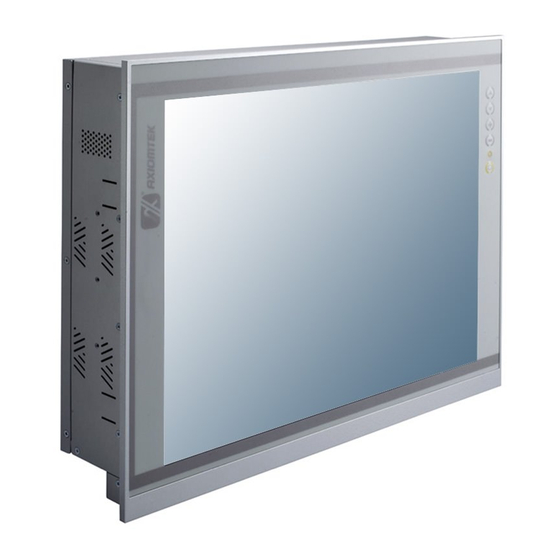
Dimensions I/O Outlets Package List General Description ® The P1177S-871 adopts a 17-inch SXGA TFT LCD with 380-nits brightness and Intel ® ® ® 3rd&2nd Core™ i7/i5/i3 series, Pentium and Celeron processors and Intel C216/Q77 chipset to provide excellent and powerful computing performance. Furthermore, P1177S-871 adopts built-in speaker and option WLAN module for wireless connectivity. -
Page 8: Specifications
P1177S-871 User’s Manual Powerful computing: Intel® 3rd Generation Core i7/i5/i3/Celeron processors ® ® ® P1177S-871 features Intel &2 Core™ i7/i5/i3 series, Pentium and Celeron processors ® and Intel C216/Q77 chipset which deliver high computing performance capability. Ivy Bridge CPU offers reliable and stable performance and rugged environment. - Page 9 P1177S-871 User’s Manual System Specification 17” SXGA(1280 X 1024)LCD 5 wired resistive Touch IP65/NEMA4 aluminum front bezel IP65 aluminum front bezel Net Weight 7 Kgs (15.43 lb) Dimension (Main Body Size) 410 x 80 x 338mm ...
-
Page 10: Dimensions And Outlines
P1177S-871 User’s Manual Dimensions and Outlines The following diagrams show the dimensions and outlines of P1177S-871. Introduction... - Page 11 P1177S-871 User’s Manual Introduction...
-
Page 12: I/O Outlets
P1177S-871 User’s Manual I/O Outlets Please refer to the following illustration for I/O locations of the P1177S-871. Function 1 x RS-232/422/485 with 5V&12V (COM1) 1 x DVI-I 2 x RJ45 for GIGA Ethernet 1 x Line-out 1 x RS-232 with 5V&12V (COM3) 2 x USB2.0... -
Page 13: Packing List
Rack mount kit x 1 (optional) Power cord x 1 DVI to VGA adaptor Fan Tunnel x 1 If you can not find the package or any items are missing, please contact Axiomtek distributors immediately. Introduction... - Page 14 P1177S-871 User’s Manual This page is intentionally left blank. Introduction...
-
Page 15: Hapter 2 Hardware A Nd Installation
P1177S-871 User’s Manual Chapter 2 Hardware and Installation The P1177S-871 provides rich I/O ports and flexible expansions for you to meet different demand. The chapter will show you how to install the hardware. It includes: Open back cover ... -
Page 16: Open
P1177S-871 User’s Manual Open back cover This section tells users how to open back cover. Please follow the steps below. Step 1 Unscrew 3 screws on the back cover and push to the right side. Please refer the photo below. -
Page 17: Serial Ports Interface
P1177S-871 User’s Manual Serial Ports Interface The P1177S-871 has four serial ports. COM1 is RS-232/422/485, while COM2, COM3 and OM4 are RS-232. The following table shows you the pin assignments of this connector: 2.2.1 COM1 Data/Power Selection (JP10) The COM1 port ha s +5V level power capability on DCD and +12V level on RI by setting this jumper. -
Page 18: Com1&Com2 Connector
P1177S-871 User’s Manual 2.2.4 COM1&COM2 Conn ector The CN15 is a double-deck DB-9 connector. The upper connector (CN15A) is for COM1 and the lower connector (CN15B) is for COM2. Note that the connectors (CN13 and CN15 A) come with powe r capability on DCD and RI pins by setting jumpers (see section 2.2.1). -
Page 19: Ethernet
P1177S-871 User’s Manual Ethernet The P1177S-871 is equipped with two high performance plug and play Ethernet interfaces (RJ-45) which are fully compliant with the IEEE 802.3 standard. Connection can be established by plugg ing one end of the Ethernet cable into this RJ-45 connector and the other end to a 1000/100/10-Base-T hub. -
Page 20: Mountings: Panel / Wall / Rack / Desktop / Vesa
P1177S-871 User’s Manual Mountings: Panel / Wall / Rack / Desktop / VESA Ther e are 5 application options for the P1177S-871, including Panel/Wall/Rack/ Desktop/VESA moun ting ways. 2.4.1 VESA-ARM / Wall-Mount / Desktop-mount P117 7S-871 p rovid es VESA mount: 75x75 mm or 100x10 0mm. -
Page 21: Panel-Mount Kit Assembly
Fixing the bracket by six screws on the left and right side. Panel-mount Kit As he P1177S-871 is design ed for panel mount appli cation. To mount the P1177S-871, the andard set of mounting kit (included in the system packaging) is n eeded Hardware and Installation... -
Page 22: Rack-Mount Kit Assembly
P1177S-871 User’s Manual .4.3 Rack-mount Kit Assembly The P1177S-871 is designed for rack mount application. To mount the P1177S-871, the standard se t of mounting kit (included in the system packaging) is needed. Step 1 Unscrew the fix screws from the left and right side of the system. -
Page 23: Hdd Installation
P1177S-871 User’s Manual HDD Installation The P1177S-871 provides a convenient Hard Disk Drive (HDD) bracket for users to install 2 x 2.5” or 1 x 3.5” SATA HDD. Please follow the steps: Step 1 Refer section 2.1 to open the back cover. - Page 24 P1177S-871 User’s Manual Step 4 Fix the HDD bracket into the main base. Step 5 Plug the power and SATA cables to connectors. Installation completes. Hardware and Installation...
-
Page 25: Dram Installation
P1177S-871 User’s Manual DRAM Installation The P1177S-871 provides two 204-pin DDR3 SO-DIMM socket that support system memory up to 16GB. Please follow steps below to install the memory modules: Step 1 Refer to section 2.1 to open the back co ver and find out DIMM socket on mainboard (MANO871). - Page 26 P1177S-871 User’s Manual Step 3 stall the SO-DIMM module into the slot and press it firmly down until it seats correctly. Step 4 The slot latches are levered upwards and latch on to the edges of the SO-DIMM. Hardware and Installation...
-
Page 27: Cpu Installation
P1177S-871 User’s Manual CPU Installation ® The P1177S-871 has an LGA1155 socket supporting Intel &2 Core™ i7/i5/i3 series, ® ® Pentium and Celeron processors and provides high computing perform ance for users. Step 1 Press the hook of lever down with your thumb and pull it to the right side to release it from retention tab. - Page 28 P1177S-871 User’s Manual Step 3 CPU aims at the socket and places the package carefully into the socket by purely vert ical motion. NOTE Never touch fragile socket contacts to avoid damage and do not touch processor sensitive contacts at any time during installation.
-
Page 29: Cpu Cooler Installation
P1177S-871 User’s Manual CPU Cooler Installation tep 1 Making sure your CPU settled co rrectly on the socket. Step 2 Screw the cooling fan supporting base onto the CPU socket on the Motherboard and make sure the CPU fan is plugged to the CPU fan connector. -
Page 30: Wireless Lan Module Installation (Optional)
P1177S-871 User’s Manual Wireless LAN Module Installation (optional) The P1177S-871 provides one wireless LAN module to install. When installing the wireless LAN module, refer to the following instructions and illustration: Step 1 Refer to section 2.1 to open the back cover and find out the wireless LAN module located. - Page 31 P1177S-871 User’s Manual Step 3 Plug in USB cable to the connec tor of WIFI module. And, find the built-in Antenna cable and connect it wire less LAN card. Step 4 Lift the rubber stopper from the top of back cover.
-
Page 32: Fan Tunnel Installation
P1177S-871 User’s Manual 2.10 Fan Tunnel Installation The P1127E-871 provides one fan tunnel to install. When installing the fan tunnel, refer to the following instructions and illustration: tep1 Spread the fan tunnel out flat. Step2 Tear the releasing paper from the dual face tape. -
Page 33: Ami Bios Setup Utility
P1177S-871 User’s Manual Chapter 3 AMI BIOS Setup Utility The AMI UEFI BIOS provides users with a built-in setup program to modify basic system configuration. All configured parameters are stored in a flash chip to save the setup information whenever the power is turned off. This chapter provides users with detailed description about how to set up basic system configuration through the AMI BIOS setup utility. -
Page 34: Main Menu
P1177S-871 User’s Manual Main Menu When you first enter the Setup Utility, you will enter the Main setup screen. You can always turn to the Main setup screen by selecting the Main tab. There are two Main Setup options. They ar escribed in this section. -
Page 35: Advanced Menu
P1177S-871 User’s Manual Advanced Menu The Advanced menu al allows u sers to set configuration of the CPU and other system devices. You can select a of the it ems in the left frame of the screen to go to the sub menus: ►... - Page 36 P1177S-871 User’s Manual ACPI Settings You can use this screen to select options for the ACPI Configuration, and change the value of the selected option. A description of the selected item appears on the right side of the screen.
- Page 37 P1177S-871 User’s Manual Trusted Computing This screen provides function for specifying the TPM settings. Security Device Support Use this item to enable or disable BIOS support for security device. Security Device Support Display current TPM status information. AMI BIOS Setup Utility...
- Page 38 P1177S-871 User’s Manual CPU Configuration This screen shows the CPU information. EIST ® Enable or disable Intel Speed Step. When enabled, CPU speed is controlled by the operating system. When disabled, CPU runs at its default speed. Turbo Mode This item is for enabling or disabling turbo mode.
- Page 39 P1177S-871 User’s Manual SATA Configuration. In this Configuration menu, you can see the currently installed hardware in the SATA ports. During s ystem boot up, the BIOS automatically detects the presence of SATA devices. SATA Controller(s) Enable or disable SATA device.
- Page 40 P1177S-871 User’s Manual PCH-FW Configuration This screen displays Management Engine (ME) Firmware infor mation. AMI BIOS Setup Utility...
- Page 41 P1177S-871 User’s Manual AMT Configuration Use this screen to configure AMT parameters. Intel AMT ® Enable or disable Intel Active Management Technology BIOS Extension. isable ME Enable or disa ble ME functionality. AMI BIOS Setup Utility...
- Page 42 P1177S-871 User’s Manual USB Configuration can use this screen to select options for the USB Configuration, and change the value of selected option. A description of the selected item appears on the right side of the scree USB Devices Display all detected USB devices.
- Page 43 P1177S-871 User’s Manual NCT6627UD Super IO Configuration You can use this screen to select options for the Super IO Configuration, and change the value of the selected option. A description of the selected item appears on the right side of the screen.
- Page 44 P1177S-871 User’s Manual NCT6627UD HW Monitor Use this screen for Smart Fan configuration and hardware health status monitoring. This screen displays the temperature of system and CPU, cooling fan speed in RPM and system voltages (VCORE, +12V, +3.3V and +5V).
-
Page 45: Chipset Menu
P1177S-871 User’s Manual Chipset Menu The Chipset menu allows users to change the advanced chipset settings. You can select any of the items in the left frame of the screen to go to the sub menus: ► PCH-IO Configuration ►... - Page 46 P1177S-871 User’s Manual PCH-IO Configuration This screen allows you to set PCH parame ters. USB Configuration Use this item for USB configuration settings. PCH Azalia Configuration Use this item for PCH Azalia configuration settings. Launch PXE OpROM policy Control the execution of UEFI and Legacy PXE OpROM.
- Page 47 P1177S-871 User’s Manual System Agent (SA) Configuration This screen shows System Agent information and provides function for specifyin g related arameters. For items marked with “”, please press <Enter> for more options. VT-d ® Enable or disable Inte chipset virtualization technology for directed I/O. VT-d can help end...
- Page 48 P1177S-871 User’s Manual Graphics Configuration Primary Display Allow you to select which graphics controller to use as the primary boot device. Primary IGFX Boot Display Allow you to select the display device which will be activated during POST. This has no effect if external graphics present.
-
Page 49: Boot Menu
P1177S-871 User’s Manual Boot Menu The Boot menu allows users to change boot options of the system. Setup Prompt Timeout Number of seconds to wait for setup activation key. 65535(0xFFFF) means indefinite waiting. Bootup NumLock State Use this item to select the power-on state for the keyboard NumLock. -
Page 50: Security Menu
P1177S-871 User’s Manual Security Menu he Security menu allows users to change the security settings for the system. Administrator Password This item indicates whether an administrator password has been set (installed or uninstalled). User Password This item indicates whether an user password has b een set (installed or uninstalled). -
Page 51: Save & Exit Menu
P1177S-871 User’s Manual Save & Exit Menu The Save & Exit menu allows users to load your system configuration with optimal or fail-safe default values. Save Changes and Exit When you have completed the system configuration changes, select this option to leave Setup and reboot the computer so the new system configuration parameters can take effect. - Page 52 P1177S-871 User’s Manual Discard Changes Select this option to quit S etup without making any permanent changes to the system onfiguration. Select Discard Chang es from the Save & Exit menu and press <Enter>. Select Yes to discard changes. estore Defaults It automatically sets all Setup options to a complete set of default settings when you select this option.
-
Page 53: Chapter 4 Drivers Installation
Chapter 4 Drivers Install ation System P1177S-871 supports Windows 7 and WES 7. To facilitate the installation of system driver, please carefully read the instructions in this chapter before start installing. Step 1 Insert Driver CD and select the “\Drivers”. - Page 54 P1177S-871 User’s Manual Driver Installation- Windows 7 The P 1177 S-871 provides a touch scr een driver that users can install it under the operating system Windows 7. To facilitate installation of the touch screen driver, you should read the instructions in this chapter carefully before you attempt installation.
- Page 55 P1177S-871 User’s Manual Step 4 Select the “Standard Calibrate” tab. Step 5 Calibrations: To adjust the display with touch panel, click “Calibration” and follow the calibrate point to do calibration; there are five points on screen for calibration. Step 6 Press OK.
-
Page 56: Embedded O.s
P1177S-871 User’s Manual Embedded O.S. The P1177S-871 prov ides the Windows 7 Embedded. The O.S. is supported devices which are listed below. WES 7 Here are supported onboard devices: Onboard Multi I/O SATA HDD PS2 Keyboard and mouse ... -
Page 57: Appendix Awatchdog Timer
P1177S-871 User’s Manual APPENDIX A WATCHDOG TIMER About Watchdog Timer After the system stops working for a while, it can be auto-reset by the watchdog timer. The integrated watchdog timer can be set up in the system reset mode by program. - Page 58 P1177S-871 User’s Manual Program Example 2E, 87 2E, 87 2E, 07 Logical Device 8 2F, 08 Activate 2E, 30 2F, 01 2E, F5 Set Minute or Second; N=08 (Min), 00(Sec) 2F, N 2E, F6 Set Value; M=00~FF 2F, M Note: If N=00h, the time base is set to second.
-
Page 59: Appendix Bintel® Iamt Settings
P1177S-871 User’s Manual APPENDIX B INTEL® IAMT SETTINGS ® ® The Intel ctive Management Technology (Intel iAMT) has decreased a major barrier to IT efficiency that uses built-in platform cap abilities and popular third-party management and security applications to allow IT a bett er discovering, healing, and protection their networked computing assets. -
Page 60: Set And Change Password
P1177S-871 User’s Manual Set and Chan ge Password You will be aske d to set a password when first log in. The default password is “admin”. You will be asked to change the password before setting ME. ® Intel IAMT Settings... -
Page 61: Intel ® Iamt We B Console
P1177S-871 User’s Manual You must confirm your new password while revising. The new password must contain: (example: !!11qqQQ) (default value). ight char ac rs ne upp er c ne lowe One number One special symbol, such as ! 、 $ or ; , (、 " , excepted) ... - Page 62 P1177S-871 User’s Manual Enter the iAMT Web. Click Remote Control, and select commands on the right side. When you have finished using the iAMT Web console, close the Web browser. ® Intel IAMT Settings...
Need help?
Do you have a question about the P1177S-871 and is the answer not in the manual?
Questions and answers