Table of Contents
Advertisement
Quick Links
Advertisement
Table of Contents

Related Manuals for AXIOMTEK PANEL5155-807


Summary of Contents for AXIOMTEK PANEL5155-807
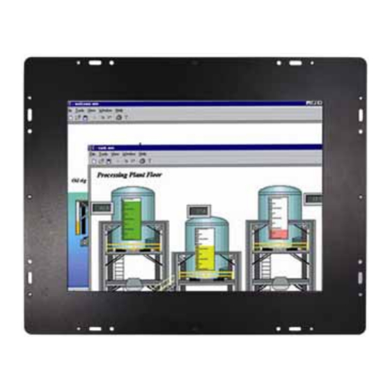
- Page 1 PANEL5155-807 Open Frame 15” TFT Touch Panel Computer User’s Manual...
- Page 2 AXIOMTEK assumes no responsibility for any inaccuracies that may be contained in this document. AXIOMTEK makes no commitment to update or to keep current the information contained in this manual. AXIOMTEK reserves the right to make improvements to this document and/or product at any time and without notice.
-
Page 3: Safety Approvals
Safety Approvals CE Marking FCC Class A FCC Compliance This equipment has been tested and complies with the limits for a Class A digital device, pursuant to Part 15 of the FCC Rules. These limits are designed to provide reasonable protection against harmful interference in a residential installation. -
Page 4: Safety Precautions
Safety Precautions Before getting started, read the following important cautions. 1. The PANEL5155-807 does not come equipped with an operating system. An operating system must be loaded first before installing any software into the computer. 2. Be sure to ground yourself to prevent static charge when installing the internal components. - Page 5 Trademarks Acknowledgments AXIOMTEK is a trademark of AXIOMTEK Co., Ltd. IBM, PC/AT, PS/2, VGA are trademarks of International Business Machines Corporation. Intel and Pentium are trademarks of Intel Corporation. MS-DOS, Microsoft C and Quick BASIC are trademarks of Microsoft Corporation.
- Page 6 This page does not contain any information.
-
Page 7: Table Of Contents
Table of Contents Disclaimers ................ii Safety Approvals..............iii FCC Compliance ..............iii Safety Precautions ............. iv C h a p t e r 1 ..............1 Introduction ................1 General Description ..........1 Specifications ............1 1.2.1 Main CPU board ..........1 1.2.2 I/O System ............2 1.2.3 System Specification ..........3 Dimensions ............3 Rear View and I/O Outlets ........5... - Page 8 P5155-807S Touch Screen .......17 3.2.1 Specification .............17 3.2.2 Driver Installation- Windows2000/XP....18 P5155-807R Touch Screen .......21 3.3.1 Specification .............21 3.3.2 Driver Installation- Windows2000/XP....22 3.3.3 Driver Installation- DOS ........24 C h a p t e r 4 ..............28 Embedded O.S. Installation..........28 Windows XP Embedded ........28 4.1.1 Calibration Touch Screen for P5155-807S..29 4.1.2...
- Page 9 Power Supply Specification ..........56 B.1 Power Supply: FSP180-50PLA1 (180W, AC 110~230V Input)...............56 B.1.1 ELECTRICAL REQUIREMENTS ........56 B.1.2 EFFICIENCY ..............59 B.1.3 ENVIRONMENTAL REQUIREMENTS......59 B.1.4 MTBF .................59 B.1.5 SAFETY ..............59 B.2 Power Supply: FSP200-62DL (200W, DC 18~36V Input)…………………………………………………………60 B.2.1 ELECTRICAL REQUIREMENTS ........60 B.2.2 EFFICIENCY ..............63 B.2.3 ENVIRONMENTAL REQUIREMENTS......63 B.2.4 MTBF .................63...
-
Page 10: Chapter 1
General Description System Specification Dimensions Back View & I/O Outlets Package List General Description The PANEL5155-807 is an Open Frame TFT Touch Panel PC which ® ® equipped with superior Pentium M/Celeron M processors and 15" XGA LCD display. The paradigmatic industrial panel computer, P5155-807, is a complete full-function and extreme cost-effective industrial HMI controller. -
Page 11: I/O System
PANEL5155-807 User’s Manual RPL/PXE Ethernet Boot ROM “Load Optimized Default” to backup customized Setting in the BIOS flash chip to prevent from CMOS battery fail One 184-pin DDR SDRAM DIMM System Memory: Maximum DDR of up to 1GB DDR266 L2 Cache: integrated in CPU... -
Page 12: System Specification
PANEL5155-807 User’s Manual 1.2.3 System Specification 15” TFT LCD Disk drive housing: − 1 x internal 3.5” drive AC power supply Heat dispensing design Net weight: − 8.8 Kgs Dimension (main body size): − 414.5 x 325.3 x 78.9mm Operating temperature: −... -
Page 14: Rear View And I/O Outlets
PANEL5155-807 User’s Manual 1.4 Rear View and I/O Outlets 1.4.1 Rear View The figure below shows the features and controls on the PANEL5155-807 Rear chassis. SEL- SEL+ Backlight ON/OFF Introduction... -
Page 15: I/O Outlet
PANEL5155-807 User’s Manual 1.4.2 I/O Outlet The following figure shows the I/O locations of the PANEL5155-807. COM 3 COM 1 & 2 Mic-in, Line-in, Line-Out USB v2.0 * 4 Power Switch AC power PS2 x 2 (KB/MS) Introduction... -
Page 16: Package List
PANEL5155-807 User’s Manual Package list When you receive the PANEL5155-807 there are following items in the package. If you can not find it, please contact AXIOMTEK distributors. 1. P5155-807 x 1 2. AC power cord x 1 3. Panel mount kit x 7 4. -
Page 17: Chapter 2
C h a p t e r Hardware Installation The PANEL5155-807 provides lots of flexible ways for you to select different configuration such as CPU, Hard Disk and more. The chapter will show you how to install the hardware. It includes:... - Page 18 PANEL5155-807 User’s Manual Rear side 2. Please be careful of membrane switch and follow below photos against cable broken. Hardware Installation...
- Page 19 PANEL5155-807 User’s Manual 3. Install the CPU and DDR DRAM in the PANEL5155-807. DRAM Hardware Installation...
-
Page 20: Hdd Installation
PANEL5155-807 User’s Manual HDD Installation The PANEL5155-807 offers a convenient drive bay module for users to install HDD. The PANEL5155-807 offers one 3.5” HDD drive for users to install. Please follow the steps: 1. Unscrew screws to remove the rear chassis. -
Page 21: Serial Port Interface
DTR, Data terminal ready RI/+5V/+12V Ring indicator GND, ground The PANEL5155-807 has an analog RGB interface connector. It is able to connect to an expansion CRT monitor, and the system can display on both the flat panel and the CRT simultaneously. -
Page 22: Mountings: Vesa/ Wall/ Panel Mount
PANEL5155-807 User’s Manual 2.6 Mountings: VESA/ Wall/ Panel mount There are four application options for the PANEL5155-807, VESA/ Wall/ Panel mountings. 2.6.1 VESA ARM The PANEL5155-807 provides two ways for VESA mount: 75x75 mm and 100x100 mm. Hardware Installation... -
Page 23: Wall Mount
PANEL5155-807 User’s Manual 2.6.2 Wall Mount The PANEL5155-807 is designed for Wall mount application. The standard set of desktop kit is included in the system packaging. Please refer to the following figure. 1. Screw 4 screws to fix wall mount bracket. -
Page 24: Panel-Mount Kit Assembly
PANEL5155-807 User’s Manual 2.6.3 Panel-Mount Kit Assembly The PANEL5155-807 is designed for panel mount application. To mount the PANEL5155-807, the standard set of mounting kit (included in the system packaging) is needed. Hardware Installation... -
Page 25: Chapter 3
PANEL5155-807 User’s Manual C h a p t e r Driver Installation System PANEL5155-807 could support with Windows 2000/XP. To facilitate installation system driver, you should read the instructions in this chapter carefully before you attempt installation. Panel series\P5155-807\Driver Select all files and follow the install procedure and press OK. -
Page 26: P5155-807S Touch Screen
PANEL5155-807 User’s Manual P5155-807S Touch Screen 3.2.1 Specification Touch Screen: ELO Surface Wave type D68054 Touch Screen Controller: Communications: RS-232 9600 (default) and 19200 Baud Rate: Resolution: 4096 x 4096, size independent +5Vdc, nominal (+4.75 to +5.25 Vdc) Power Input: Positional Accuracy: Less than 0.080 inch (2.03 mm) -
Page 27: Driver Installation- Windows2000/Xp
PANEL5155-807 User’s Manual 3.2.2 Driver Installation- Windows2000/XP The touch screen of PANEL5155-807S provides a driver for use with Windows 2000/XP. To facilitate installation of the touch screen driver, you should read the instructions in this chapter carefully before you attempt installation. - Page 28 PANEL5155-807 User’s Manual Driver Installation...
- Page 29 PANEL5155-807 User’s Manual Calibration: To adjust the display with touch panel, click “Align” and follow the calibrate point to do calibration; there are three points on screen for calibration. Press YES. Driver Installation...
-
Page 30: P5155-807R Touch Screen
PANEL5155-807 User’s Manual P5155-807R Touch Screen 3.3.1 Specification For 5-wire Analog Resistive type Touch Screen: Touch Screen Controller: DMC9000 RS-232 Communications: 19200 baud rate fixed Baud Rate: 1024 x 1024 (10 bit A/D converter inside) Resolution: 5V to 12V DC... -
Page 31: Driver Installation- Windows2000/Xp
PANEL5155-807 User’s Manual 3.3.2 Driver Installation- Windows2000/XP The touch screen of PANEL5155-807R provides a driver for use with Windows 2000/XP. To facilitate installation of the touch screen driver, you should read the instructions in this chapter carefully before you attempt installation. - Page 32 PANEL5155-807 User’s Manual Select the “Standard Calibrate” tab Driver Installation...
-
Page 33: Driver Installation- Dos
PANEL5155-807 User’s Manual Calibration: To adjust the display with touch panel, click “Calibration” and follow the calibrate point to do calibration; there are five points on screen for calibration. Press OK. 3.3.3 Driver Installation- DOS Using “INSTALL.EXE” utility to install PenMount software driver. - Page 34 PANEL5155-807 User’s Manual Identify the communication port and IRQ number 1. For the first time installation, or changing PenMount Touch Screen’s port, PMDETECT (e.g. C:\PENMOUNT\PMDETECT) to check the COM port and IRQ number. PMDETECT will save the correct data to PMOUSE.CFG file for further use.
- Page 35 PANEL5155-807 User’s Manual mapped results by choose “3” DRAWING TEST under PM.BAT Initializing the PenMount driver If you don’t have the initialization commands in AUTOEXEC.BAT, initialize PenMount C:\PENMOUNT\PMINIT) controller before you use the PenMount Touch Screen. The display will show the initialization message: PenMount V7.06 Copyright(c) SALT International Corp.
- Page 36 PANEL5155-807 User’s Manual This page does not contain any information. Driver Installation...
-
Page 37: Chapter 4
PANEL5155-807 User’s Manual C h a p t e r Embedded O.S. Installation Windows XP Embedded Supported devices are as follows: Multiple I/O: 3 x UARTs compliant Serial Ports (No COM Mouse support) IDE: IDE HDD USB 2.0: 4 x USB Ports Keyboard &... -
Page 38: Calibration Touch Screen For P5155-807S
PANEL5155-807 User’s Manual 4.1.1 Calibration Touch Screen for P5155-807S This image includes a Touch Screen on COM4. To calibrate it, do the following steps: 1. Start\Programs\Elo Calibration 2. Follow the on-screen directions 3. Save the registry and restart the system 4.1.2 Calibration Touch Screen for P5155-807R... -
Page 39: Windows Ce.net 5.0
PANEL5155-807 User’s Manual Windows CE.NET 5.0 Supported devices are as follows: System Memory Support 128MB 256MB Multiple I/O Parallel Port 4 x UARTs compliant Serial Ports (No COM Mouse support) IrDA Port USB 2.0 4 x USB Host Ports Keyboard & Mouse... -
Page 40: Sbc86807 Bios Setup
PANEL5155-807 User’s Manual A p p e n d i x SBC86807 BIOS Setup Appendix A describes the different settings available in the Award BIOS that comes with the SBC86807 CPU card. Also, the instructions on how to set up the BIOS configuration are contained in this chapter. - Page 41 PANEL5155-807 User’s Manual In general, the arrow keys are used to highlight items, <Enter> to select, the <PgUp> and <PgDn> keys to change entries, <F1> for help and <Esc> to quit. Phoenix – AwardBIOS CMOS Setup Utility Standard CMOS Features...
-
Page 42: Standard Cmos Setup
PANEL5155-807 User’s Manual A.2.1 Standard CMOS Setup “Standard CMOS Setup” is used to record some basic hardware configurations in the computer system and set the system clock and error handling. If the motherboard is already installed in a working system, there is no need to enter this option. However, the Standard... - Page 43 PANEL5155-807 User’s Manual Date The date format is <day>, <date> <month> <year>. Press <F3> to show the calendar. The day of week, from Sun to Sat, determined by the BIOS, is read only The date, from 1 to 31 (or the maximum allowed...
- Page 44 PANEL5155-807 User’s Manual If there is no hard disk drive installed, select NONE and press <Enter>. Drive A type/Drive B type The category identifies the types of floppy disk drive A or drive B installed in the computer. None No floppy drive installed 5.25 inch PC-type standard drive;...
-
Page 45: Advanced Bios Features
PANEL5155-807 User’s Manual A.2.2 Advanced BIOS Features This section is used to configure and improve the system and set up some system features according to the user’s preference. Phoenix – Award BIOS CMOS Setup Utility Advanced BIOS Features Hard Disk Boot Priority... - Page 46 PANEL5155-807 User’s Manual Virus Warning This item protects the boot sector and partition table of the hard disk against accidental modifications. If an attempt is made, the BIOS will halt the system and display a warning message. If this occurs, the user can either continue the operation or run an anti-virus program to locate and remove the problem.
- Page 47 PANEL5155-807 User’s Manual During POST, BIOS will determine the floppy disk drive type, 40 or 80 tracks. 360Kb type is 40 tracks while 720Kb, 1.2MB and 1.44MB are all 80 tracks. The default value is “Enabled”. BIOS searches for floppy disk drive to determine if it is Enabled 40 or 80 tracks.
- Page 48 PANEL5155-807 User’s Manual 15 characters per second 20 characters per second 24 characters per second 30 characters per second Typematic Delay (Msec) This option sets the display time interval from the first to the second character when holding a key. The default value is “250”.
-
Page 49: Advanced Chipset Features
PANEL5155-807 User’s Manual A.2.3 Advanced Chipset Features Since the features in this section are related to the chipset on the CPU board and are completely optimized, changing the default settings in this setup table are not recommended unless the user is well oriented with the chipset features. - Page 50 PANEL5155-807 User’s Manual DRAM Timing By SPD This item is selected depending on whether the board has paged DRAMs or EDO (extended data output) DRAMs. System BIOS Cacheable Selecting “Enabled” allows caching of the system BIOS ROM at F0000h-FFFFFh, resulting in better system performance. However, if any program writes to this memory area, a system error may result.
-
Page 51: Integrated Peripherals
PANEL5155-807 User’s Manual A.2.4 Integrated Peripherals This option sets the hard disk configuration, mode and port. Phoenix – Award BIOS CMOS Setup Utility Integrated Peripherals OnChip IDE Device Enabled Item Help Onboard Device Enabled SuperIO Device Enabled Menu Level Onboard UART 3... - Page 52 PANEL5155-807 User’s Manual Phoenix – Award BIOS CMOS Setup Utility Onboard Device USB controller Enabled Item Help USB 2.0 controller Enabled USB Keyboard Support Enabled Menu Level USB Mouse Support Disabled AC 97 Audio Auto Init Display first Onboard/AGP : Move...
- Page 53 PANEL5155-807 User’s Manual The four PIO (Programmed Input/Output) fields sets a PIO mode (0-4) for each of the four IDE devices that the onboard IDE interface supports. Modes 0 through 4 provide successively increased performance. Auto mode, the system automatically determines the best mode for each device.
-
Page 54: Power Management Setup
PANEL5155-807 User’s Manual A.2.5 Power Management Setup The Power Management Setup is to save energy of the system effectively. It will shut down the hard disk and turn OFF video display after a period of inactivity. Phoenix – Award BIOS CMOS Setup Utility... - Page 55 PANEL5155-807 User’s Manual The choice: User Define, Min Saving, Max Saving. Video Off Method This determines the manner in which the monitor is blanked. This causes the system to turn off the vertical and V/H SYNC + horizontal synchronization ports and write blanks Blank to the video buffer.
- Page 56 PANEL5155-807 User’s Manual Upon turning OFF system from the power switch, this option will delay the complete system power OFF Delay 4 Sec. sequence by approximately 4 seconds. Within this delay period, system will temporarily enter into Suspend Mode enabling you to restart the system at once.
-
Page 57: Pnp/Pci Configuration
PANEL5155-807 User’s Manual A.2.6 PNP/PCI Configuration This section describes the PCI bus system configuration. PCI or Personal Computer Interconnect is a system which allows I/O devices to operate at speeds nearing the speed of the CPU when communicating with its own special components. This section covers some very technical items, and it is strongly recommended that only experienced users should make changes to the default settings. -
Page 58: Pc Health Status
PANEL5155-807 User’s Manual A.2.7 PC Health Status This section is to monitor the current hardware status of core voltages. This is available only if there is hardware monitoring mechanism onboard. Phoenix – Award BIOS CMOS Setup Utility PC Health Status Current GMCH Temp. -
Page 59: Frequency/Voltage Control
PANEL5155-807 User’s Manual A.2.8 Frequency/Voltage Control CMOS Setup Utility-Copyright © 1984-2001 Award Software Frequency/Voltage Control Auto Detect DIMM/PCI Clk Enabled Spread Spectrum Disabled Menu Level : Move Enter: Select +/-/PU/PD: Value F10: Save ESC: Exit F1: General Help F5: Previous Values F6: Fail-Safe Defaults F7: Optimized Defaults... -
Page 60: Load Fail-Safe Defaults
PANEL5155-807 User’s Manual A.2.9 Load Fail-Safe Defaults This option is to load the troubleshooting default values permanently stored in the BIOS ROM. These default settings are non-optimal and disable all high-performance features. Phoenix – Award BIOS CMOS Setup Utility Standard CMOS Features... -
Page 61: Load Optimized Defaults
PANEL5155-807 User’s Manual A.2.10 Load Optimized Defaults This option is to load the default values to the system configuration. These default settings are optimal and enable all high performance features. Phoenix – Award BIOS CMOS Setup Utility Standard CMOS Features... -
Page 62: Set Supervisor/User Password
PANEL5155-807 User’s Manual A.2.11 Set Supervisor/User Password Either supervisor or user password, or both of them can be set in this option. The differences between them are: supervisor password: can enter and change the options of the setup menus. user password: just can enter but do not have the right to change the options of the setup menus. -
Page 63: Save & Exit Setup
PANEL5155-807 User’s Manual A.2.12 Save & Exit Setup This is to determine whether or not to accept the modifications. Typing “Y” quits the setup utility and saves all changes into the CMOS memory. Typing “N” brigs back to Setup utility. -
Page 64: Exit Without Saving
PANEL5155-807 User’s Manual A.2.13 Exit Without Saving Select this option to exit the Setup utility without saving the changes made in this session. Typing “Y” will quit the Setup utility without saving the modifications. Typing “N” will return to Setup utility. -
Page 65: Power Supply Specification
PANEL5155-807 User’s Manual Appendix B Power Supply Specification Power Supply: FSP180-50PLA1 (180W, AC 110~230V Input) B.1.1 ELECTRICAL REQUIREMENTS OUTPUT ELECTRICAL REQUIREMENTS The subject power supply will meet all electrical specifications below, over the full operation temperature range and dynamic load regulation. - Page 66 PANEL5155-807 User’s Manual LOAD CAPACITY SPECIFICATIONS The cross regulation defined as follows, the voltage regulation limits DC include DC Output ripple & noise. LOAD +3.3V +12V -12V ALL MAX HHHH 4.5A 9.0A 9.0A 0.8A +5V MAX LHLL 0.3A 12.0 A 1.5A...
- Page 67 PANEL5155-807 User’s Manual SHORT CIRCUIT PROTECTION Output short circuit is defined to be a short circuit load of less than 0.1 ohm. In the event of an output short circuit condition on +3.3V, +5V or +12V output, the power supply will shutdown and latch off. The power...
-
Page 68: Efficiency
PANEL5155-807 User’s Manual TTL signal asserted (high state): greater than 4.75V while sourcing 500uA. High state output impedance: less or equal to 1Kohm from output to common. POWER GOOD @ 100 –500mSec. 115/230V,FULL LOAD POWER FAIL @115/230V, FULL 1 mSec. minimum LOAD B.1.2... -
Page 69: Power Supply: Fsp200-62Dl (200W, Dc 18~36V Input)
PANEL5155-807 User’s Manual Power Supply: FSP200-62DL (200W, DC 18~36V Input) B.2.1 ELECTRICAL REQUIREMENTS OUTPUT ELECTRICAL REQUIREMENTS The subject power supply will meet all electrical specifications below, over the full operation temperature range and dynamic load regulation. OUTPUT RATING Output Nominal... - Page 70 PANEL5155-807 User’s Manual LOAD CAPACITY SPECIFICATIONS The loading of cross regulation test is defined as follows. LOAD +3.3V +12V -12V 5VSB 0.0A 0.0A 0.0A 0.0A 0.0A 0.0A 1.0A 0.5A 0.0A 0.0A 12.0A 1.0A 0.5A 0.0A 0.0A 0.0A 12.0A 0.5A 0.0A 0.0A...
- Page 71 PANEL5155-807 User’s Manual SHORT CIRCUIT PROTECTION Output short circuit is defined to be a short circuit load of less than 0.1 ohm. In the event of an output short circuit condition on +3.3V, +5V or +12V output, the power supply will shutdown and latch off. The power...
-
Page 72: Efficiency
PANEL5155-807 User’s Manual TTL signal asserted (high state): greater than 4.75V while sourcing 500uA. High state output impedance: less or equal to 1Kohm from output to common. POWER GOOD @ 100 –500mSec. 115/230V,FULL LOAD POWER FAIL @115/230V, FULL 1 mSec. minimum LOAD B.2.2...
Need help?
Do you have a question about the PANEL5155-807 and is the answer not in the manual?
Questions and answers