Table of Contents
Advertisement
Quick Links
Advertisement
Table of Contents

Related Manuals for AXIOMTEK P1177E-842


Summary of Contents for AXIOMTEK P1177E-842
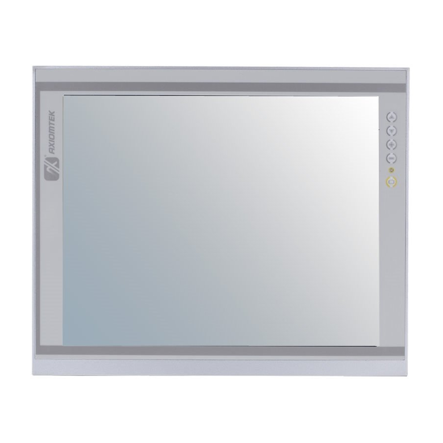
- Page 1 P1177E-842 All-in-One 17” SXGA TFT Expandable PANEL PC User’s Manual...
-
Page 2: Disclaimers
Axiomtek does not make any commitment to update the information in this manual. Axiomtek reserves the right to change or revise this document and/or product at any time without notice. No part of this document may be reproduced, stored in a retrieval system, or transmitted, in any form or by any means, electronic, mechanical, photocopying, recording, or otherwise, without the prior written permission of Axiomtek Co., Ltd. -
Page 3: Safety Precautions
When handling boards and components, wear a wrist-grounding strap, available from most electronic component stores. Trademarks Acknowledgments Axiomtek is a trademark of Axiomtek Co., Ltd. ® Windows is a trademark of Microsoft Corporation. IBM, PC/AT, PS/2, VGA are trademarks of International Business Machines Corporation. -
Page 4: Table Of Contents
Table of Contents Disclaimers ..................... ii Safety Precautions ..................iii Chapter 1 Introduction ..........1 General Description ................1 Specifications ..................2 Dimensions and Outlines ..............4 I/O Outlets .................... 6 Packing List ..................7 Chapter 2 Hardware and Installation ...... 9 Open back cover ................ - Page 5 Advanced Menu ................. 31 Chipset Menu ..................45 Security Menu ..................51 Boot Menu ..................52 Save & Exit Menu ................53 Chapter 4 Drivers Installation ......55 System ....................55 Touch Screen ..................55 Embedded O.S................... 59...
- Page 6 This page is intentionally left blank.
-
Page 7: Chapter 1 Introduction
Therefore, P1177E-842 is especially suitable for most rugged industrial environments. Expandable for PCIe (PCI optional) P1177E-842 has 1 PCIe (1 PCI optional) for expansion purpose. User can easily plug in standard half-size PCI or PCIe card for any requirement. -
Page 8: Specifications
P1177E-842 User’s Manual Speaker and WLAN Antenna Supported P1177E-842 features built-in speakers for kiosk application to display multimedia content program. It also supports WLAN module (optional) antenna for wireless network connectivity. Low power consumption computing: Intel® Celeron® Processor J1900 ®... - Page 9 P1177E-842 User’s Manual System Specification 17” SXGA (1280x1024) LCD 5 wired resistive Touch IP65/NEMA4 aluminum front bezel Net Weight 6.3 Kgs (13.89 lb) Dimension (Main Body Size) 410 mm (16.14”) (W) x 92 mm (3.62”) (D) x 338mm (13.30”) (H) ...
-
Page 10: Dimensions And Outlines
P1177E-842 User’s Manual Dimensions and Outlines The following diagrams show the dimensions and outlines of P1177E-842. Introduction... - Page 11 P1177E-842 User’s Manual Introduction...
-
Page 12: I/O Outlets
P1177E-842 User’s Manual I/O Outlets Please refer to the following illustration for I/O locations of the P1177E-842. Function 1 x AC Plug PS/2 Mouse PS/2 Keyboard 1 x RS-232/422/485 (COM1) 1 x RS-232/422/485 (COM2) 1 x VGA 1 x HDMI 1 x RJ45 for GIGA Ethernet 1 x USB3.0, 1 x USB2.0... -
Page 13: Packing List
Panel mount kit x 7 Wall/VESA mount kit x 1 (optional) Rack mount kit x 1 (optional) Power cord x 1 If you can not find the package or any items are missing, please contact Axiomtek distributors immediately. Introduction... - Page 14 P1177E-842 User’s Manual This page is intentionally left blank. Introduction...
-
Page 15: Hardware And Installation
P1177E-842 User’s Manual Chapter 2 Hardware and Installation The P1177E-842 provides rich I/O ports and flexible expansions for you to meet different demand. The chapter will show you how to install the hardware. It includes: Open Back Cover ... -
Page 16: Open
P1177E-842 User’s Manual Open back cover This section tells users how to open back cover. Please follow the steps below. Step 1 Unscrew 3 screws on the back cover and push to the right side. Please refer the photo below. -
Page 17: Serial Ports Interface
CTS# Ethernet The P1177E-842 is equipped with two high performance plug and play Ethernet interfaces (RJ-45) which are fully compliant with the IEEE 802.3 standard. Connection can be established by plugging one end of the Ethernet cable into this RJ-45 connector and the other end to a 1000/100/10-Base-T hub. -
Page 18: Mountings: Panel / Wall / Rack / Desktop / Vesa
There are 5 application options for the P1177E-842, including Panel/Wall/Rack/ Desktop/VESA mounting ways. 2.4.1 VESA-ARM / Wall-Mount / Desktop-mount The P1177E-842 provides VESA mount: 75x75 mm or 100x100mm. Screw six screws to fix the kit in the back chassis. ▲... -
Page 19: 2.4.2 Panel-Mount Kit Assembly
Fixing the bracket by six screws on the left and right side. 2.4.2 Panel-mount Kit Assembly The P1177E-842 is designed for panel mount application. To mount the P1177E-842, the standard set of mounting kit (7pcs included in the system packaging) is needed. -
Page 20: 2.4.3 Rack-Mount Kit Assembly
P1177E-842 User’s Manual 2.4.3 Rack-mount Kit Assembly The P1177E-842 is designed for rack mount application. To mount the P1177S-871, the standard set of mounting kit (included in the system packaging) is needed. Step 1 Unscrew the fix screws from the left and right side of the system. -
Page 21: Hdd Installation
P1177E-842 User’s Manual HDD Installation The P1177E-842 provides a convenient Hard Disk Drive (HDD) bracket for users to install 2.5” 1 x 3.5” or 2.5” SATA HDD. Please follow the steps: Step 1 Refer section 2.1 to open the back cover. - Page 22 P1177E-842 User’s Manual Step 4 Fix the HDD bracket into the main base. Step 5 Plug the power and SATA cables to connectors. Installation completes. Hardware and Installation...
-
Page 23: Dram Installation
P1177E-842 User’s Manual DRAM Installation The P1177E-842 provides one 204-pin DDR3L SO-DIMM sockets that support system memory up to 8GB. Please follow steps below to install the memory modules: Step 1 Refer to section 2.1 to open the back cover and find out DIMM socket on mainboard (MANO842). - Page 24 P1177E-842 User’s Manual Step 3 The slot latches are levered upwards and latch on to the edges of the SO-DIMM. Hardware and Installation...
-
Page 25: Wireless Lan Module Installation (Optional)
P1177E-842 User’s Manual Wireless LAN Module Installation (optional) The P1177E-842 provides one wireless LAN module to install. When installing the wireless LAN module, refer to the following instructions and illustration: Step 1 Refer to section 2.1 to open the back cover and find out PCIe Mini-Card slot located. - Page 26 P1177E-842 User’s Manual Step 3 Find the built-in Antenna cable and connect it wireless LAN card. Step 4 Lift the rubber stopper from the top of back cover. Step 5 Install the antenna on the antenna connector. Hardware and Installation...
-
Page 27: Add-On Card Installation
P1177E-842 User’s Manual Add-on Card Installation The P1177E-842 provides a riser card (PCIe interface) for 1 x PCIe or 1 x PCI slots expansion. The riser card assembly can accommodate both half-size expansion cards. To install the riser card, refer to the following figure and instructions below: Step 1 Refer section 2.1 to open the back cover and unscrew 2 screws, and then... - Page 28 P1177E-842 User’s Manual Step 3 Secure the metal bracket of the card to the system case with four screws. Installations complete. NOTE: Please use the standard size of add-on card to avoid conflicting the mechanism. Hardware and Installation...
-
Page 29: Board Layout
P1177E-842 User’s Manual Board Layout Hardware and Installation... -
Page 30: Rear I/O
P1177E-842 User’s Manual 2.10 Rear I/O Front Audio Header (CN31) COM2 Connector (CN18) Internal USB Header (CN3) mSATA Slot (CN28) AT/ATX Power Mode Select Jumper (JP4) PCI-Express x1 Slot (CN26) COM3 Data/Power Select Jumper (JP11) PCI-Express Mini Card Connector (CN27) COM3~COM6 Headers (CN19~CN22) SATA 2.0 Connector (CN4) -
Page 31: Jumper Settings
P1177E-842 User’s Manual 2.11 Jumper Settings Jumper is a small component consisting of jumper clip and jumper pins. Install jumper clip on 2 jumper pins to close. And remove jumper clip from 2 jumper pins to open. The following illustration shows how to set up jumper. -
Page 32: Clear Cmos Select (Jp1)
P1177E-842 User’s Manual 2.11.1 Clear CMOS Select (JP1) This jumper allows you to clear the Real Time Clock (RTC) RAM in CMOS. You can clear the CMOS memory of date, time, and system setup parameters by erasing the CMOS RTC RAM data. -
Page 33: Com1 Rs-232/422/485 Mode Select (Jp5, Jp6, Jp7)
P1177E-842 User’s Manual 2.11.4 COM1 RS-232/422/485 Mode Select (JP5, JP6, JP7) Use these jumpers (3x2-pin p=2.54mm) to set COM1 port to operate as RS-232, RS-422 or RS-485 communication mode. Function Setting JP5 1-2 close RS-232 mode JP6 3-5, 4-6 close... - Page 34 P1177E-842 User’s Manual This page is intentionally left blank. Hardware and Installation...
-
Page 35: Ami Bios Setup Utility
P1177E-842 User’s Manual Chapter 3 AMI BIOS Setup Utility The AMI UEFI BIOS provides users with a built-in setup program to modify basic system configuration. All configured parameters are stored in a flash chip to save the setup information whenever the power is turned off. This chapter provides users with detailed description about how to set up basic system configuration through the AMI BIOS setup utility. -
Page 36: Main Menu
P1177E-842 User’s Manual Main Menu When you first enter the setup utility, you will enter the Main setup screen. You can always return to the Main setup screen by selecting the Main tab. System Time/Date can be set up as described below. -
Page 37: Advanced Menu
P1177E-842 User’s Manual Advanced Menu The Advanced menu also allows users to set configuration of the CPU and other system devices. You can select any of the items in the left frame of the screen to go to the sub menus: ►... - Page 38 P1177E-842 User’s Manual ACPI Settings You can use this screen to select options for the ACPI configuration, and change the value of the selected option. A description of the selected item appears on the right side of the screen.
- Page 39 P1177E-842 User’s Manual Super IO Configuration You can use this screen to select options for the Super IO Configuration, and change the value of the selected option. A description of the selected item appears on the right side of the screen.
- Page 40 P1177E-842 User’s Manual COM1 Serial Port Enable or disable serial port 1. The optimal setting for base I/O address is 3F8h and for interrupt request address is IRQ4. Change Settings Select an optimal setting for serial port. AMI BIOS Setup Utility...
- Page 41 P1177E-842 User’s Manual Hardware Monitor This screen monitors hardware health status. This screen displays the temperature of system and CPU, cooling fans speed in RPM and system voltages (VCC_CPU, VCC_DDR, +12V, +5V, +3.3V and VBAT). AMI BIOS Setup Utility...
- Page 42 P1177E-842 User’s Manual Smart Fan Function This screen allows you to select the fan mode. CPU_FAN1 Mode This item allows you to select the fan mode, which can be set to Full on Mode, Manual Mode, Auto PWM Mode or Auto RPM Mode.
- Page 43 P1177E-842 User’s Manual Display Configuration Primary IGFX Boot Display Select the video device which will be activated during POST (Power-On Self Test). The default is Auto. LVDS Panel Type Select LVDS panel resolution; see the selection options in image above.
- Page 44 P1177E-842 User’s Manual Power Button Control Restore AC Power Loss This item decides the state of system when AC power is resupplied after a power failure. Mode options are Power Off, Power On and Last State. Soft-Off by PWR-BTTN - Instant-Off: The system will shut down instantly when the power button is pressed.
- Page 45 P1177E-842 User’s Manual S5 RTC Wake Settings Wake system from S5 Enable or disable system wake on alarm event. It allows you to wake up the system in a certain time. Select Fixed Time to set the system to wake on the specified time. Use <> <>...
- Page 46 P1177E-842 User’s Manual CPU Configuration This screen shows the CPU Configuration, and you can change the value of the selected option. Socket 0 CPU Information This item is for CPU information. Limit CPUID Maximum This item allows user to limit the maximum value of CPUID. In Windows XP environment, this item should be disabled.
- Page 47 P1177E-842 User’s Manual IDE Configuration In the IDE Configuration menu, you can see the currently installed hardware in the SATA ports. During system boot up, the BIOS automatically detects the presence of SATA devices. Serial-ATA (SATA) Enable or disable the SATA controller feature.
- Page 48 P1177E-842 User’s Manual OS Configuration OS Selection This item allows user to select the proper Operating System. AMI BIOS Setup Utility...
- Page 49 P1177E-842 User’s Manual CSM Configuration CSM Support Enable or disable CSM (Compatibility Support Module) support. PXE BootRom Enable or disable the Preboot eXecution Environment (PXE) boot ROM function of the onboard LAN chip during system boots up. AMI BIOS Setup Utility...
- Page 50 P1177E-842 User’s Manual USB Configuration Legacy USB Support Use this item to enable or disable legacy support for USB devices. The default setting is Enabled. Auto option disables legacy support if no USB devices are connected. Disable option will keep USB devices available only for EFI applications.
-
Page 51: Chipset Menu
P1177E-842 User’s Manual Chipset Menu The Chipset menu allows users to change the advanced chipset settings. You can select any of the items in the left frame of the screen to go to the sub menus: ► North Bridge ►... - Page 52 P1177E-842 User’s Manual North Bridge IGD Turbo Enable Enable or disable the IGD Turbo feature. This screen shows system memory information. AMI BIOS Setup Utility...
- Page 53 P1177E-842 User’s Manual South Bridge This screen allows users to configure parameters of South Bridge chipset. AMI BIOS Setup Utility...
- Page 54 P1177E-842 User’s Manual Azalia HD Audio Disable=Azalia will be unconditionally Disable Enable=Azalia will be unconditionally Enable AMI BIOS Setup Utility...
- Page 55 P1177E-842 User’s Manual USB Configuration XHCI Mode Enable/Disable or select Auto/Smart Auto XHCI Mode feature. USB 2.0(EHCI) can select Enable when XHCI mode is disabled. AMI BIOS Setup Utility...
- Page 56 P1177E-842 User’s Manual PCI Express Configuration PCI Express port 0~3 can select Enable or Disable Speed can select Gen1/Gen2 or Auto AMI BIOS Setup Utility...
-
Page 57: Security Menu
P1177E-842 User’s Manual Security Menu The Security menu allows users to change the security settings for the system. Administrator Password This item indicates whether an administrator password has been set (installed or uninstalled). User Password This item indicates whether a user password has been set (installed or uninstalled). -
Page 58: Boot Menu
P1177E-842 User’s Manual Boot Menu The Boot menu allows users to change boot options of the system. Setup Prompt Timeout Number of seconds to wait for setup activation key. 65535(0xFFFF) means indefinite waiting. Bootup NumLock State Use this item to select the power-on state for the keyboard NumLock. -
Page 59: Save & Exit Menu
P1177E-842 User’s Manual Save & Exit Menu The Save & Exit menu allows users to load your system configuration with optimal or fail-safe default values. Save Changes and Reset When you have completed the system configuration changes, select this option to leave Setup and reboot the computer so the new system configuration parameters can take effect. - Page 60 P1177E-842 User’s Manual Boot Override Select a drive to immediately boot that device regardless of the current boot order. Launch EFI Shell from filesystem device Attempt to launch EFI Shell application (Shellx64.efi) from one of the available filesystem devices. AMI BIOS Setup Utility...
-
Page 61: Chapter 4 Drivers Installation
Chapter 4 Drivers Installation System P1177E-842 supports Windows 7 / Windows 8.1 / WES7 / WE8S. To facilitate the installation of system driver, please carefully read the instructions in this chapter before start installing. Insert Driver CD and select the “\Drivers”. - Page 62 Driver Installation- Windows 7 / 8.1 The P1177E-842 provides a touch screen driver that users can install it under the operating system Windows 7. To facilitate installation of the touch screen driver, you should read the instructions in this chapter carefully before you attempt installation.
- Page 63 P1177E-842 User’s Manual Click “Configure” Step 4 Select the “Standard Calibrate” tab. Step 5 Drivers Installation...
- Page 64 P1177E-842 User’s Manual Step 6 Calibrations: To adjust the display with touch panel, click “Calibration” and follow the calibrate point to do calibration; there are five points on screen for calibration. Step 7 Press OK. Drivers Installation...
-
Page 65: Embedded O.s
P1177E-842 User’s Manual Embedded O.S. The P1177E-842 provides the Windows 7 Embedded and Windows Embedded 8 Standard. The O.S. is supported devices which are listed below. WES7 / WE8S Here are supported onboard devices: Onboard Multi I/O ...
Need help?
Do you have a question about the P1177E-842 and is the answer not in the manual?
Questions and answers