
Subscribe to Our Youtube Channel
Related Manuals for Gilson 223


Summary of Contents for Gilson 223
- Page 1 223 Sample Changer User’s Guide ©2014 Gilson, Inc. | All rights reserved. LT1932-06...
-
Page 3: Table Of Contents
Technical Specifications ................. . 1-8 223 Sample Changer User’s Guide... - Page 4 Power Connection ................. .2-15 Table of Contents-2 223 Sample Changer User’s Guide...
- Page 5 Not Detecting Liquid Level ................5-4 223 Sample Changer User’s Guide...
- Page 6 Replacement Parts ..................A-5 Racks Table of Contents-4 223 Sample Changer User’s Guide...
- Page 7 The following safety precautions must be observed during all phases of operation, service, and repair of the instrument. Failure to comply with these precautions or with specific warnings elsewhere in the user’s guide violates safety standards of design, manufacture, and intended use of the instrument. Gilson assumes no liability for the customer’s failure to comply with these requirements.
- Page 8 WARNING indicates a potentially hazardous situation which, if not avoided, may result in serious injury CAUTION indicates a potentially hazardous situation which, if not avoided, may result in minor or moderate injury NOTICE indicates a potentially hazardous situation which, if not avoided, may result in equipment damage Safety-2 223 Sample Changer User’s Guide...
-
Page 9: Safety
Z-arm may contain dangerous substances, do not interfere in the work area of the instrument until it has completed its procedures. Replacement Parts Be sure to use only replacement parts mentioned in the user’s guide. Do not repair the instrument or change parts not listed in the user’s guide. 223 Sample Changer User’s Guide Safety-3... -
Page 11: Sécurité
Le non-respect de ces précautions ou des avertissements spécifiques mentionnés dans ce guide compromet les normes de sécurité de conception, de fabrication et d’utilisation prévue de l’instrument. Gilson décline toute responsabilité en cas d’’incapacité du client à se conformer à ces exigences. - Page 12 CAUTION indique une situation potentiellement dangereuse qui, si elle n’est pas évitée, peut entrainer des blessures mineures à modérées NOTICE indique une situation potentiellement dangereuse qui, si elle n’est pas évitée, peut entrainer des dégâts matériels Sécurité-2 223 Sample Changer User’s Guide...
-
Page 13: Levage
Pièces détachées Assurez-vous de n’utiliser exclusivement que les pièces détachées mentionnées le guide d’utilisation. Ne tentez pas de réparer ou remplacer des pièces ne figurant pas dans ce guide. 223 Sample Changer User’s Guide Sécurité-3... -
Page 15: Introduction
Introduction This chapter provides information on the following topics: • Description • Unpacking • Technical Specifications 223 Sample Changer User’s Guide... -
Page 16: Description
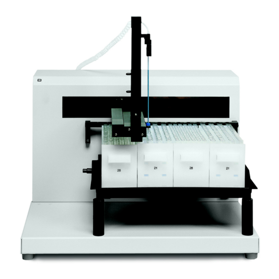
Introduction Description The 223 Sample Changer is an XYZ robot that can automate sample handling procedures. It is controlled via a program running on a computer. 223 Sample Changer 223 Sample Changer User’s Guide... -
Page 17: Unpacking
Unpacking The 223 Sample Changer arrives with all major components already assembled except for auxiliary parts such as the vertical arm, probe, tray, racks, etc. Keep the original container and packing assembly in case the sample changer must be returned. -
Page 18: Accessories
Probe holder/guide kit; includes probe holder, guide and probe connecting nut (part number 27072001) for 1.5 mm outer diameter probes. 19061041 Probe holder/guide kit; includes probe holder, guide and probe connecting nut (part number 23074002) for Teflon probes. 223 Sample Changer User’s Guide... - Page 19 The tubing/cable support rod restrains excess transfer tubing. Place the tubing/cable support rod on top of the sample changer. A magnet at the bottom of the rod holds it into place on top of the sample changer. Part Number Description 190713 Tubing/cable support rod 223 Sample Changer User’s Guide...
- Page 20 A diverting valve can be mounted on the sample changer. Part Number Description 190711 Diverting valve assembly for 223 Sample Changer. Includes mounting bracket, tubing, and two tubing/cable clips Transfer Tubing Based on your requirements, you also received transfer tubing, ordered separately. Refer to Appendix A, Replacement Parts and Accessories for part numbers.
- Page 21 1907142 Port bar 223 antlers code 30-series 1907143 Port bar 223 antlers code 0-series for one Code 0, 7, 8, or 9 rack Microplate Holder To use microplates with the sample changer, you must install the microplate holder. You can use standard or deep microplates.
-
Page 22: Technical Specifications
Please be aware of the following before operating the sample changer. Changes or modifications to the liquid handler not expressly approved by Gilson could void the warranty. This instrument complies with part 15 of the FCC Rules. Operation is subject to the following two conditions: (1) This instrument may not cause harmful interference, and (2) this instrument must accept any interference received, including interference that may cause undesired operation. - Page 23 Conformity document for the current standards to which the instrument has been tested. Sampler Type X/Y/Z with stationary rack design Vertical Punch Strength 1 kg (2 lbs.) Weight 18.6 kg (41 lbs.) Technical Specifications - 223 Sample Changer (Page 2 of 2) 223 Sample Changer User’s Guide...
-
Page 24: Installation
Installation This chapter details the steps for setting up the 223 Sample Changer, which includes: • Arm Locking Screw Removal • Vertical Arm Installation • Probe Installation • Rinse Station and Port Bar Installation • Tray Installation • Rack Installation •... -
Page 25: Arm Locking Screw Removal
Insert the arm locking screw into its storage location on the rear panel. Replace the plastic plug on the side panel. Ensure that the horizontal arm can move by pushing it to the left as far as it will go. 223 Sample Changer User’s Guide... -
Page 26: Vertical Arm Installation
While slightly moving the probe holder bracket up and down, push the control rod until it clicks into position. 10 Re-insert the white plastic plug. 11 Re-attach the cover plate to the front of the horizontal arm. 223 Sample Changer User’s Guide... -
Page 27: Probe Installation
Connect the transfer tubing from the dilutor, if installed, to the tubing fitting. Slide the probe assembly into the probe holder on the vertical arm making sure that the probe is centered over the probe guide. Secure the probe by tightening the probe retaining screw. 223 Sample Changer User’s Guide... -
Page 28: Rinse Station And Port Bar Installation
(a peristaltic pump, for example). Attach the port bar to the upper position of the front standoffs on the front of the sample changer using the knurled screws. 223 Sample Changer User’s Guide... -
Page 29: Tray Installation
Attach one end of the drain tubing (part number 470343706) to the drain outlet and place the other in a drain receptacle, located lower than the tray. Tray Removal To remove the tray, first lift it straight up and then bring it towards you. 223 Sample Changer User’s Guide... -
Page 30: Rack Installation
A bracket must be attached to the microplate holder before the microplate is installed. Assembly and installation of the microplate holder depends on the type of microplates to be used. Refer to the appropriate instructions on the next few pages. 223 Sample Changer User’s Guide... - Page 31 Install the microplate holder, in the upper position on the front standoffs, using the two knurled screws. Note: If a port bar is installed, install the microplate holder in front of the port bar. port front standoff microplate holder 223 Sample Changer User’s Guide...
- Page 32 If installed, remove the polypropylene tray. Install the microplate holder, in the lower position of the front standoffs, below the port bar if installed. Use the two knurled screws supplied with the microplate holder. port front standoff microplate holder 223 Sample Changer User’s Guide...
-
Page 33: Accessory Installation
Separate the probe guide from the filler port assembly by unscrewing it. The probe guide has a hexagonal head. Insert the probe guide into a mounting hole on the port bar and tighten. Attach the bottom portion of the filler port assembly to the probe guide. 2-10 223 Sample Changer User’s Guide... -
Page 34: Liquid Level Detector
If necessary, lower the probe so you can route the tubing through the clip. Attach the transfer tubing from each dilutor to the side ports. 223 Sample Changer User’s Guide 2-11... -
Page 35: Rear Panel Connections
Installation Rear Panel Connections Rear Panel Diagram Input/Output (I/O) contact ports SW1 (unit ID) selector SW2 (baud rate/configuration) selector Gilson Serial Input/Output Channel (GSIOC) port Keypad port RS-232 port Power receptacle Power switch Fuse drawer 10 Keypad power RS-232 Port The RS-232 port is used to transfer information between the sample changer and a computer. -
Page 36: Gsioc Port
GSIOC cable for linking additional GSIOC instruments Connect the other female connector, located on the same end as the male connector, to the Gilson module. Tighten the retaining screws. If connecting more than one Gilson module, use the male connector to attach an additional GSIOC cable. Use the female connectors to connect each Gilson module. -
Page 37: Input/Output Ports
Connect the terminal block connector to the sample changer. Push the connector in as far as it will go. It is designed to fit snugly into its receptacle. Connect the opposite ends of the wires to the other device(s). Be sure to match connections. GROUND Label each cable to identify the purpose of the connection. 2-14 223 Sample Changer User’s Guide... -
Page 38: Sw 1 (Unit Id) Selector
The unit ID identifies the sample changer to software packages that can issue GSIOC commands to the sample changer. The unit ID is set to 10. There is no need to change this number unless it is the same as that assigned to another Gilson instrument that is also connected along the GSIOC. -
Page 39: Operation
Operation This chapter provides the following information: • How to Start Up the sample changer • How to use the 223 Setup Utility 223 Sample Changer User’s Guide... -
Page 40: Start Up
Power the sample changer ON using the power switch located on the rear panel. The indicator light on the front panel illuminates. If the indicator light begins blinking, there is a problem with the sample changer. See Indicator Light Not Illuminated on page 5-3. 223 Sample Changer User’s Guide... -
Page 41: 223 Setup Utility
The 223 Setup Utility allows you to review and, if necessary, change the configuration options set for the sample changer. When you execute the 223 Setup Utility from the computer, the following screen with menu tabs appears: •... -
Page 42: Homing
X or Y direction. To store changes to the X and Y offsets, click OK. Or, to display the X and Y offsets currently set in the instrument’s memory, click Cancel. Click Home to home the instrument. 223 Sample Changer User’s Guide... -
Page 43: Arm Travel
Z-arm controls the amount of travel in the Z-axis. To store the selected Z-height settings to the sample changer’s memory, click OK. To display the Z-height settings currently set in the sample changer’s memory, click Cancel. 223 Sample Changer User’s Guide... -
Page 44: Contacts
The Contacts tab allows you to toggle output contacts to determine if the correct contact connections have been made to peripheral devices to be controlled by the 223 Sample Changer. Before using this tab, you need to connect the peripheral device’s inputs to the appropriate output pair on the sample changer. -
Page 45: Xyz Coordinates
First, click Disable Motors. Then, manually move the horizontal and vertical arms to a location on the sample changer’s work area. Finally, manually lower or raise the probe to the appropriate height. The 223 Setup Utility displays the X, Y, and Z coordinates. -
Page 46: Maintenance
To obtain optimum performance and maximum life from the sample changer, keep it well-maintained. The 223 Sample Changer is intended to be used in a laboratory environment by trained technical personnel. This chapter contains the following information to help you maintain your sample changer: •... -
Page 47: Clean The Sample Changer
The sample changer should be cleaned occasionally using a dry, clean cloth. Or, if necessary, use a cloth dipped in soapy water. If liquid is accidentally spilled on the sample changer, wipe the instrument using a dry, clean cloth. 223 Sample Changer User’s Guide... -
Page 48: Part Replacement
Install the new probe into the tubing fitting. Slide the probe assembly into the probe holder making sure that the probe is centered over the probe guide. Secure the probe by tightening the probe retaining screw. Re-attach and tighten the transfer tubing’s 1/4"-28 fitting. 223 Sample Changer User’s Guide... -
Page 49: Fuse
Insert the fuse drawer into its receptacle on the rear panel. A blown fuse may indicate the existence of another problem in the instrument. If the replacement fuses blow, do not try others. 223 Sample Changer User’s Guide... -
Page 50: Check Position Alignment
Maintenance Check Position Alignment The 223 Setup Utility (Adjust XY tab), described on page 3-4, allows you to test whether the instrument is properly adjusted and to make minor adjustments to the X- and Y-axis offsets if needed. You may need to use the options under this tab if the probe is not accessing the transfer port, filler port, or the vessels in the installed racks. -
Page 51: Transport The Sample Changer
Re-insert the control rod as far as it will go. While inserting the rod, you may need to rotate the rod back and forth slightly to get it to pass through the vertical arm’s gearing and motor drive socket. Re-attach the plate to the front of the horizontal arm. 223 Sample Changer User’s Guide... -
Page 52: Troubleshooting
Troubleshooting This chapter provides information on the following topics: • Error Messages • Mechanical Troubleshooting • Electrical Troubleshooting • Liquid Level Detector Troubleshooting 223 Sample Changer User’s Guide... -
Page 53: Error Messages
X-offset out of range Run the 223 Setup Utility (Adjust XY tab) to correct the problem. Y-offset out of range Run the 223 Setup Utility (Adjust XY tab) to correct the problem. -
Page 54: Mechanical
Issue buffered ~9 command to reset NV-RAM and initialize default parameters. Sample Changer Blows Fuses A blown fuse may indicate the existence of another problem in the instrument. If the replacement fuses blow, do not try others. 223 Sample Changer User’s Guide... -
Page 55: Liquid Level Detector
Check if liquid is detectable. Liquid level detection works only if there is electrical conductivity in your liquid. Liquid level detecting will not work with most non-polar liquids. For intermediate polarity liquids and polar liquids, check the sensitivity setting in the 223 Setup Utility. •... -
Page 56: Replacement Parts And Accessories
(tip dimensions: 2 x 1.1 x 0.4 mm ID). 27067362 Side-entry probe (septum-piercing); 220.5 x 1.5 x 1.1 mm. Probes for 183 mm Vertical Arm—Teflon Part Number Description 27067369 Teflon-coated probe for non-metal applications. Dimensions: 220 x 0.9 mm ID. 223 Sample Changer User’s Guide... -
Page 57: Probes For 123 Mm Vertical Arm-Stainless Steel
Constricting tip probe; 93.5 x 1.5 x 1.1 mm. Requires probe holder/guide kit (part number 19061040). Probes for 56 mm Vertical Arm—Titanium Part Number Description Beveled-edge probe (septum-piercing); 95 x 0.7 x 0.42 mm. Requires probe sleeve (part number 27067133 27067132) and probe holder guide/kit (part number 19061040). 223 Sample Changer User’s Guide... -
Page 58: Double Probe Kit
Probe holder/guide kit; includes probe holder, guide and probe connecting nut (part number 27072001) 19061040 for 1.5 mm outer diameter probes. Probe holder/guide kit; includes probe holder, guide and probe connecting nut (part number 23074002) 19061041 for Teflon probes. 223 Sample Changer User’s Guide... -
Page 59: Transfer Tubing
Gilson instruments: the GSIOC Device Driver to 2106171 extend MS DOS or PC DOS to use Gilson devices, and sample programs written in BASICA, Turbo Pascal, Microsoft Pascal and C which demonstrate how to write programs to address Gilson instruments. Use with Model 605 RS-232 Adapter or 506C System Interface Module. -
Page 60: Safety Shield
Holder for four standard or deep-well microplates 1907142 Port bar 223 antlers code 30-series 1907143 Port bar 223 antlers code 0-series for one Code 0, 7, 8, or 9 rack 2704429 Thermostating cuvette: one required per Code 30-series thermostated rack. 2949694... - Page 61 You can configure the sample changer with a variety of rack types and sizes. The sample changer can hold a maximum of four Code 20-series racks or thermostated Code 30-Series racks. To make your own rack, order the Polypropylene unperforated rack kit (part number 150499). 223 Sample Changer User’s Guide...
- Page 62 Part number: 2707401 Note: Requires installation of rack holder (part number 1907143). Chapter 2, Installation. Code 8 rack For 120 vessels Material: polypropylene Vessels and maximum capacity: 6 x 32 mm tubes (0.3 mL) Part number: 270438 223 Sample Changer User’s Guide...
- Page 63 Vessels and maximum capacity: 10 x 100 mm tubes (4.5 mL) Part number: 150425 Code 21 rack For 60 vessels Material: polypropylene Vessels and maximum capacity: 13 x 100 mm tubes (9 mL) Part number: 150422 223 Sample Changer User’s Guide...
- Page 64 Note: Each of the reception cavities contains four positioning and retaining clips. Code 23 rack For 44 mini-scintillation vials Material: polypropylene Vessels and maximum capacity: 17 x 55 mm vials (6.8 mL) 17 x 65 mm vials (8 mL) Part number: 150426 223 Sample Changer User’s Guide...
- Page 65 Vessels and maximum capacity: 28 x 57 mm (20 mL) Part number: 150427 Code 28 rack For 108 vessels Material: polypropylene Vessels and maximum capacity: 10 x 65 mm tubes (3 mL) 10 x 75 mm tubes (3.5 mL) Part number: 150420 223 Sample Changer User’s Guide...
- Page 66 Vessels and maximum capacity: 7 x 30 mm (0.5 mL) Part number: 2704341 Code 30 rack For 60 vessels Material: aluminum Vessels and maximum capacity: 12 x 32 mm vials (2 mL) Part number: 2704430 223 Sample Changer User’s Guide...
- Page 67 Part number: 2704431 Code 31P rack For 108 vessels Material: polypropylene Vessels and maximum capacity: 7 x 40 mm tubes (0.7 mL) Part number: 2704531P Note: Requires installation of rack holder (part number 1907142). Chapter 2, Installation. 223 Sample Changer User’s Guide...
- Page 68 Part number: 2704433 Code 33P rack For 14 scintillation vials Material: polypropylene Vessels and maximum capacity: 28 x 57 mm (20 mL) Part number: 2704533P Note: Requires installation of rack holder (part number 1907142). Chapter 2, Installation. 223 Sample Changer User’s Guide...
- Page 69 For 71 vessels and one scintillation vial Material: polypropylene Vessels and maximum capacity: 12 x 32 mm (2 mL) 28 x 60 mm (20 mL) Part number: 2704535P Note: Requires installation of rack holder (part number 1907142). See Chapter 2, Installation. 223 Sample Changer User’s Guide...
- Page 70 Part number: 2704437 Code 38 rack Thermostated rack for 96 microvials and one scintillation vial Material: aluminum Vessels and maximum capacity: 7 x 41 mm (0.7 mL) 28 x 60 mm (20 mL) Part number: 2704438 B-10 223 Sample Changer User’s Guide...
Need help?
Do you have a question about the 223 and is the answer not in the manual?
Questions and answers