
Subscribe to Our Youtube Channel
Related Manuals for Eneo TVB-2080V2812IR


Summary of Contents for Eneo TVB-2080V2812IR
- Page 1 Quick Installation Guide 1/2.8” HD-TVI Camera, Day&Night, 1920x1080, WDR 2.8-12mm, Infrared, 12/24V TVB-2080V2812IR...
-
Page 2: Table Of Contents
Table of content Parts supplied .......................5 Part names ........................6 Installation instructions ....................7 Pan & Tilt adjustments ..............................8 Zoom & Focus adjustments ............................9 Power supply connections ............................10 Operating instructions ....................11 Using OSD controller..............................11 Description of the joystick operation ....................... 11 Description of the D-ZOOM adjustment .................... - Page 3 Safety instructions General safety instructions • Before switching on and operating the system, first read this safety advice and the operating instructions. • Keep the operating instructions in a safe place for later use. • Installation, commissioning and maintenance of the system may only be carried out by authorised individuals and in accordance with the installation instructions - ensuring that all applicable standards and guidelines are followed.
- Page 4 Class A device note This is a Class A device. This device can cause malfunctions in the living area; in such an event, the operator may need to take appropriate measures to compensate for these. WEEE (Waste Electronical & Electronic Equipment) Correct Disposal of This Product (Applicable in the European Union and other European countries with separate collection systems).
-
Page 5: Parts Supplied
Parts supplied • Camera • Plastic Anchor: 6 x 30mm (4pcs) • Mounting Screw: 4 x 30mm (4pcs) • Cable Signal Sticker • Operating Instruction • Mounting Template • Assembly Screw: 4 x 15mm (4pcs) • Torque Wrench: 3mm (1pc) •... -
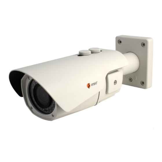
Page 6: Part Names
Part names Sunshield bolt Sunshield Power cable OSD setup control cover Dual window Easy bracket Bracket Rear case Front case Lock/unlock screw Focus Zoom Lock/Unlock screw Torque wrench... -
Page 7: Installation Instructions
Installation instructions CAUTION: The camera’s base should be attached to a structural object, such as concrete, hard wood, wall stud or ceiling rafter that supports the weight of the camera. If necessary use appro- priate mounting material (e.g. anchors) instead of the material enclosed with the camera. -
Page 8: Pan & Tilt Adjustments
CAUTION: Extreme care should be taken NOT to scratch the window in front of lens. Care should be taken the cable is NOT to be damaged, kinked or exposed in the hazardous area. Do not expose the camera directly to a strong light source such as the sun or spot light. -
Page 9: Zoom & Focus Adjustments
2. Tilt limit: Tilt is limited to 0°(2°) min ~ 90° max. for wall(ceiling) installation respec- tively with reference to the wall(ceiling) when the inclination of camera module is 0°, that is, the image is aligned horizontally. 90° 88° on the wall on the ceiling 3. -
Page 10: Power Supply Connections
Power supply connections Make sure the power is removed before the installation. Camera can work with either 24AC or 12VDC, dual voltage power. Primary and secondary grounds are completely isolated to avoid the possible ground-loop problems. VIDEO (BNC) AC24V/DC12V (Red wire) AC24V/GND (Black wire) RTX+/RS485 (White wire) RTX-/RS485 (Gray wire) -
Page 11: Operating Instructions
Operating instructions Using OSD controller Setup menu can be accessed and controlled by OSD control joy stick on the side of cam- era unit. Five commands are available with the joy stick. Cover Open SUB-OUT OSD Control Joy Stick Video Sub-out Connector ZOOM Description of the joystick operation 1. -
Page 12: Osd Menu Startup
2. ▼ : Zoom Out OSD menu startup Press ‘●’ (OSD menu Joy stick key) down for about 2 seconds to access the setup menu mode. • RET: Returns to the previous menu. • EXIT: Exits the menu setting without save. •... - Page 13 MAIN DEFAULT DESCRIPTION SCENE ENHANCE provides the several ways to enhance the video in the various environments with the settings in NORMAL, WDR, D-WDR, BLC and HLC. NORMAL – Optimized for the normal indoor and outdoor in the good lighting condition. WDR –...
-
Page 14: Further Information
Further information The manual is also available from the eneo web site at www.eneo-security.com. - Page 15 Inhalt Lieferumfang .......................18 Bezeichnungen von Gerätekomponenten ...............19 Installationsanweisungen ..................20 Einstellung von Schwenkung und Neigung ......................21 Zoom- und Fokuseinstellung ............................ 23 Stromversorgungsanschlüsse ............................ 23 Betriebsanleitung .......................25 Bildschirmmenü-Steuerung verwenden ....................... 25 Beschreibung der Joystick-Bedienung ..................... 25 Beschreibung der D-Zoom-Einstellung ....................25 Bildschirmmenü...
- Page 16 Sicherheitsanweisungen Sicherheitshinweise allgemein • Bevor Sie das System anschließen und in Betrieb nehmen, lesen Sie zuerst diese Sicherheitshinweise und die Betriebsanleitung. • Bewahren Sie die Betriebsanleitung sorgfältig zur späteren Verwendung auf. • Montage, Inbetriebnahme und Wartung des Systems darf nur durch dafür autorisierte Personen vorge- nommen und entsprechend den Installationsanweisungen - unter Beachtung aller mitgeltenden Normen und Richtlinien - durchgeführt werden.
- Page 17 • Bei abgedunkelter Umgebung und direktem Blick in den IR-Scheinwerfer ist ein Sicherheitsabstand von > 1 m zum Scheinwerfer einzuhalten. • Unsichtbare LED Strahlung nicht direkt mit optischen Instrumenten (z.B. Lupe, Vergrößerungsglas oder Mikroskop) betrachten, da sie eine Augengefährdung verursachen kann, LED Klasse 1M. •...
-
Page 18: Lieferumfang
Lieferumfang • Kamera • Kunststoffdübel: 6 x 30 mm (4 St.) • Befestigungsschraube: 4 x 30 mm (4 St.) • Kabelsignal-Aufkleber • Betriebsanleitung • Bohrschablone • Montageschraube: 4 x 15 mm (4 St.) • Inbusschlüssel: 3 mm (1 St.) • Steckverbinder: (1 St.) •... -
Page 19: Bezeichnungen Von Gerätekomponenten
Bezeichnungen von Gerätekomponenten Bolzen für Sonnenschutzdach Sonnenschutzdach Netzkabel Abdeckung für Bildschirmmenüsteuerung Doppelglasiges Fenster "Easy Bracket"-Halterung Kamerahalter Hinteres Gehäuse Vorderes Gehäuse Schraube zum Verriegeln/Entriegeln Fokus Zoom Schraube zum Verriegeln/Entriegeln Inbusschlüssel... -
Page 20: Installationsanweisungen
Installationsanweisungen ACHTUNG: Die Kamerahalterung sollte an einem Bauelement wie etwa Beton, Hartholz, einem Wandständer oder Deckenbal- ken befestigt werden, welches das Gewicht der Kamera trägt. Verwenden Sie, falls erforderlich, geeignetes Befestigungsmateri- al (z.B. Dübel) anstelle des mitgelieferten Materials. 1. Halten Sie die Bohrschablone an die Installationsstelle und bohren Sie die Löcher in Decke oder Wand, falls erforderlich. -
Page 21: Einstellung Von Schwenkung Und Neigung
Befestigungsschraube 1: 4 x 30mm Montageschraube: 4 x 15 mm Inbusschlüssel Kabeldurchgang ACHTUNG: Achten Sie besonders darauf, das Fenster vor dem Objektiv NICHT zu verkratzen. Es muss sorgfältig darauf geachtet werden, das Kabel NICHT zu beschädigen, zu knicken oder Gefahrenbereichen auszusetzen. Setzen Sie die Kamera nie direkt einer starken Lichtquelle wie der Sonne oder einem Scheinwerfer aus. - Page 22 • Stellen Sie den Betrachtungswinkel der Kamera ein und ziehen Sie die Schraube am Halter fest. Anpassung des Betrachtungswinkels mit einem Halter Schraube zum Verriegeln/Entriegeln Inbusschlüssel 1. Schwenkwinkel: Der Schwenkwinkel ist auf +/- 90° begrenzt. 90° 90° 2. Neigungswinkel: Die Neigung ist bei Wand- (bzw. Decken)-Installation auf min. 0°(2°) bis max.
-
Page 23: Zoom- Und Fokuseinstellung
3. Drehwinkel (horizontale Bildausrichtung): Der Drehwinkel ist begrenzt auf max. +/-90°. ±90° Zoom- und Fokuseinstellung Verwenden Sie den mitgelieferten Inbusschlüssel. • Drehen Sie den Fokusring in Richtung "N" (Nah) oder "∞" (Fern), bis der schärfste Fokus erreicht ist. • Drehen Sie zum Erweitern des Betrachtungswinkels den Zoomring in Richtung "W" (Weitwinkel) und für eine nähere Betrachtung in Richtung "T"... - Page 24 Bringen Sie den Signalbelegungs-Aufkleber an einer sichtbaren Stelle als Referenz für die Anschlussverkabelung an.
-
Page 25: Betriebsanleitung
Betriebsanleitung Bildschirmmenü-Steuerung verwenden Zugriff und Steuerung des Konfigurationsmenüs können über den Joystick zur Bild- schirmmenü-Steuerung an der Kamera und einen Service Monitor erfolgen. Fünf Befehle stehen mit dem Joystick zur Verfügung. Abdeckung öffnen SUB-OUT Joystick zur Bildschirmmenü-Steuerung Video Sub-out Anschluss ZOOM Beschreibung der Joystick-Bedienung 1. -
Page 26: Bildschirmmenü Starten
1. ▲ : Heranzoomen 2. ▼ : Herauszoomen Bildschirmmenü starten Halten Sie die Taste '●' (Taste für Bildschirmmenü-Joystick) ca. 2 Sekunden lang gedrückt, um in das Setup-Menü zu gelangen. • RET: Kehrt zum vorherigen Menü zurück. • EXIT: Verlässt die Menüeinstellungen ohne zu speichern. •... - Page 27 MAIN DEFAULT (Standard) BESCHREIBUNG SCENE ENHANCE bietet mehrere Möglichkeiten das Video in unterschied- lichen Umgebungen, mit den Einstellungen NORMAL, WDR, D-WDR, BLC und HLC zu verbessern. NORMAL - Optimiert für die normale Innen- und Außenanwendung bei guten Lichtverhältnissen. WDR - Verbessert die Sicht in über- und unterbelichteten Bereichen durch doppelte Bildaufzeichnung mit langer und kurzer Belichtung.
-
Page 28: Weitere Informationen
UTC CONTROL (UTC Steuerung), LANGUAGE (Sprache), OUTPUT SELECT (Signalauswahl), FACTORY DEFAULT (Werkseinstellungen). SAVE & EXIT – Menü nach Speicherung der Parameter verlassen. EXIT – EXIT Verlassen des Menüs ohne zu speichern. Weitere Informationen Dieses Handbuch ist auch auf der eneo-Webseite unter www.eneo-security.com verfügbar. - Page 29 Table of content Matériel livré .......................32 Noms des pièces ......................33 Instructions d'installation ..................34 Réglages Panoramique/Inclinaisons ........................35 Ajustement du zoom et de la mise au point ....................... 37 Connexions d'alimentation ............................37 Mode d'emploi ......................39 Utilisation d'une commande OS ..........................39 Description du fonctionnement de la manette de contrôle ............
- Page 30 Instructions de sécurité Consignes de sécurité générales • Avant de brancher et de mettre en service le système, veuillez lire d'abord ces consignes de sécurité ainsi que la notice d'instructions. • Conservez soigneusement la notice d'instructions en vue d'une utilisation ultérieure. •...
- Page 31 • Une distance de sécurité > 1 m doit être respectée par rapport au projecteur dans un environnement sombre, quand on regarde directement dans le projecteur IR. • Les rayons invisibles des LED ne doivent pas être observés directement avec des instruments optiques (par ex.
-
Page 32: Matériel Livré
Matériel livré • Caméra • Chevilles en plastique : 6 x 30mm (4x) • Vis de fixation : 4 x 30mm (4x) • Étiquette de signalisation du câble • Mode d'emploi • Gabarit de perçage • Vis de fixation : 4 x 15mm (4x)) •... -
Page 33: Noms Des Pièces
Noms des pièces Boulon du pare-soleil Pare-soleil Câble d'alimentation Couvercle de commande de configuration OSD Double vitre Easy bracket Support Panneau arrière Panneau avant Vis de verrouillage/déverrouillage Objectif Zoom Vis de verrouillage/ déverrouillage Clé Torx... -
Page 34: Instructions D'installation
Instructions d'installation ATTENTION : La base de la caméra doit être fixée à une surface solide, co mme du bois dur, un mur, pilier ou poutre au plafond apte à supporter le poids de la caméra dôme. Si nécessaire, utiliser un matériel de fixation (ancrages) plus adéquat au lieu du matériel fourni avec la caméra. -
Page 35: Réglages Panoramique/Inclinaisons
Vis de montage 1 : 4 x 30 mm Vis de montage : 4 x 15 mm Clé Torx Sorties de câbles ATTENTION : Il faudra veiller à ne pas érafler la vitre devant l'objectif. Veillez à ne PAS endommager, déformer ou exposer le câble dans une zone dangereuse. - Page 36 Réglage de l'angle de vision à l'aide d'un support Vis de verrouillage/ déverrouillage Clé Torx 1. Limite de panoramique : le panoramique est limité à +/- 90°. 90° 90° 2. Limite d'inclinaison : l’inclinaison est limitée à une fourchette de 0° (2°) min ~ 90° max.
-
Page 37: Ajustement Du Zoom Et De La Mise Au Point
3. Limite d'inclinaison (alignement horizontal de l'image) Inclinaison limitée à +/-90° max. ±90° Ajustement du zoom et de la mise au point Utiliser la clé Torx fournie. • Ajuster le réglage de la mise au point à “N” (Near-proche) ou“∞” (Far-loin) afin d'ob- tenir la mise au point la plus nette. - Page 38 Apposer l'étiquette de l'affectation de signal en un lieu visible pour référence de câblage.
-
Page 39: Mode D'emploi
Mode d'emploi Utilisation d'une commande OS Le menu de configuration peut être consulté et contrôlé soit en utilisant la manette de contrôle de l'affichage à l'écran situé sur le côté de la caméra. Cinq fonctions de com- mande sont disponibles avec la manette. Couvercle ouvert SUB-OUT Manette de commande OSD... -
Page 40: Démarrage Du Menu Osd
1. ▲ : Zoom In (agrandissement) 2. ▼ : Zoom Out (zoom arrière) Démarrage du menu OSD Appuyer sur ‘●’ (touche de la manette du menu OSD) pendant environ 2 secondes pour accéder au mode de menu configuration. • RET : retour au menu précédent.EXIT : permet de quitter le menu de configuration sans sauvegarder. - Page 41 MAIN (Menu principal) PAR DÉFAUT DESCRIPTION SCENE ENHANCE permet d'améliorer la qualité de la vidéo en fonction de l'environ- nement, grâce aux réglages en position NORMAL, WDR, D-WDR, BLC et HLC. NORMAL – Optimisé pour un extérieur ou un intérieur normal dans de bonnes conditions d’...
-
Page 42: Complément D'information
OUTPUT SELECT (Sélection sortie) et FACTORY DEFAULT (valeur par défaut) SAVE & EXIT – Quitter le menu après avoir enregistré les paramètres. EXIT – Quitter QUITTER le menu sans sauvegarder. Complément d'information Le manuel complet est également proposé sur le site Web d’eneo : www.eneo-security. com. - Page 44 VIDEOR E. Hartig GmbH Exclusive distribution through specialised trade channels only. VIDEOR E. Hartig GmbH Carl-Zeiss-Straße 8 63322 Rödermark/Germany Tel. +49 (0) 6074 / 888-0 Technical changes reserved Fax +49 (0) 6074 / 888-100 www.videor.com...
Need help?
Do you have a question about the TVB-2080V2812IR and is the answer not in the manual?
Questions and answers