
Subscribe to Our Youtube Channel
Related Manuals for Endura EVC


Summary of Contents for Endura EVC
- Page 1 IN-VEHICLE CHARGERS Single Unit In-Vehicle Charger FOR TWO-WAY RADIO BATTERIES User Manual For EVC Models...
-
Page 3: Table Of Contents
Table of Contents Topic Page Introduction Important Caution Features 4 - 5 Installation Charging A Radio Battery 7 - 8 USB Charging Port Status LED Summary Fault Conditions And Advisements 10 - 11 Specifications Warranty Optional Accessories Installation Notes... -
Page 4: Introduction
12V – 24V source in a vehicle. EVC models are radio specific and provide a precision fit with the battery. The model you have purchased will charge Li-Ion / LiPo batteries only or Li-Ion, LiPo and NiMH batteries based on the batteries available for your radio. -
Page 5: Important
Read all Caution statements below and this User Manual before attempting to install the EVC or charge a battery. Check to make sure the EVC model is compatible with your radio battery and battery chemistry before installing. Always charge new batteries completely before initial use. Recycle batteries when they can no longer be used. -
Page 6: Caution
† Do not open or make any modifications to the EVC. Use only the DC power cable supplied. Always secure the radio (or battery) in the radio holder with the tie-down strap before the vehicle, trailer, or train goes in motion. -
Page 7: Features
(see Optional Accessories). Charging contacts. Status LED (radio battery). Tie-down strap. † Retaining hook for connecting tie-down strap. USB charging port and power-on LED. † Some EVC models have a fabric strap with grommets in place of the elastic cord. - Page 8 EVC Features (continued) Screws and spacers for fastening EVC to vehicle. Connection point for DC power cable. 10. DC power cable (EVC-HW).
-
Page 9: Installation
Use the 4 screws provided to fasten the EVC to the dash or wall of your vehicle. If needed, place a rubber spacer over each screw on the back side of the charger to help stabilize the unit. -
Page 10: Charging A Radio Battery
A battery may be charged while on or off the radio. Always use the tie-down strap to secure the radio or battery before your vehicle is driven. After the EVC is installed, switch vehicle power on and place a battery in the charger. The status LED will illuminate RED continuously to indicate normal charging. -
Page 11: Usb Charging Port
To charge a device, simply connect it to the USB port with a compatible USB cable. The LED above the USB port illuminates RED when the EVC is connected to power and indicates the port has sufficient input voltage to charge your device. -
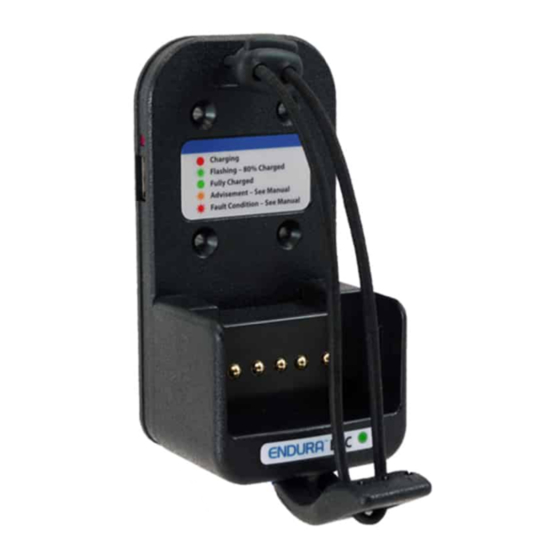
Page 12: Status Led Summary
Battery cannot be charged, see “Advisements”. Solid RED Normal battery charging. Flashing RED Requires immediate attention, see “Fault Conditions”. Flashing GREEN Battery charge level approximately 80%. Solid GREEN Battery fully charged and in maintenance mode. *Cold battery detection not available on some EVC models. -
Page 13: Fault Conditions And Advisements
Indicates battery contact is “open” and current is not passing through the (+) and (-) contacts on the battery. This warning is provided after the initial diagnostic stage is complete. Check 2 Times EVC compatibility with your battery. Flashes RED Battery temperature is 45°C (113° F) or above. Charging has terminated, remove battery from charger. - Page 14 Fault Conditions & Advisements (continued) The flash patterns for fault conditions are as follows: LED Pattern Advisement Solid ORANGE Brief reset period for charger after battery is removed. Allow the LED to go off before inserting another battery. (Battery removed.) Solid ORANGE Indicates battery is too cold when initially inserted.
-
Page 15: Specifications
Dimensions (L x W x D) 133.9mm x 66.4mm x 58.3mm / 5.3” x 2.4” x 2.3” (varies slightly by model) *EVC-BK2 requires 14V / 1A minimum to fully charge radio battery. Input voltage from 12V – 14V will result in the battery being undercharged. -
Page 16: Warranty
Warranty & Service During Warranty Power Products Unlimited, LLC (PPU) warrants this product to be free from defects in workmanship and materials for two years from date of purchase by the end user. This warranty applies to the original pur- chaser and is void if the product has been altered, misused, damaged, neglected, or if repair is required because of normal wear and tear. -
Page 17: Optional Accessories
Part Number Description LEVCA-M Multi-directional dash mounting bracket with 4-hole AMPS mounting pattern. LEVCA-MHD Heavy duty floor mounting bracket with 4-hole AMPS mounting pattern. EVC-HW DC power cable for all EVC models (included). EVC-MB4 Mounting base for 4 EVC chargers. -
Page 18: Installation Notes
Installation Notes... - Page 20 IN-VEHICLE CHARGERS 2170 Brandon Trail • Alpharetta, GA 30004 www.powerproducts.com ©2020 Power Products Unlimited, LLC. Endura Chargers By Power Products Power Products, Endura are trademarks of Power Products Unlimited, LLC. Smart – Adaptable – Reliable™ All rights reserved.
Need help?
Do you have a question about the EVC and is the answer not in the manual?
Questions and answers