
Related Manuals for Endura EC1


Summary of Contents for Endura EC1
-
Page 1: User Manual
™ Single Unit Rapid Charger FOR RECHARGEABLE TWO-WAY RADIO BATTERIES User Manual Desktop Models: EC1 / EC1-V2 In-Vehicle Models: EC1M / EC1M-V2... -
Page 3: Table Of Contents
ENDURA EC1 / EC1M CHARGERS Table of Contents Topic Page Introduction Important (read before use) Caution (read before use) Replacing A Charging Pod EC1 Features Accessories For In-Vehicle Installation In-Vehicle Installation (EC1M) Charging A Battery Fault Conditions & Advisements Warranty And Service... -
Page 4: Introduction
Thank you for purchasing an Endura™ EC charger. There are four EC charger models covered in this User Manual: EC1 / EC1M and EC1-V2 / EC1M-V2. Model EC1 is for desktop use and includes an AC to DC power supply. Model EC1M is for in-vehicle use and includes the accessories needed for installation in a vehicle. -
Page 5: Important (Read Before Use)
If you wish to replace the charging pod in the future, check the model number on the product label (EC1 or EC1-V2) to ensure the replacement pod selected is compatible with your model. For a complete list of charging pods available or to confirm pod compatibility, contact a Power Products dealer, visit www.powerproducts.com, or call... -
Page 6: Caution (Read Before Use)
Caution Based on the pod selected, EC models can charge Li-Ion / LiPo and / or NiMH / NiCd batteries. If the pod is designed for Li-Ion / LiPo only, do not attempt to charge NiMH / NiCd batteries. If the pod is designed for NiMH / NiCd only, do not attempt to charge Li-Ion / LiPo batteries. - Page 7 Caution (continued) Use only the power supply or vehicle power adapter provided with the EC model. If a replacement is required, see section Accessories. Use of other power supplies may damage the charger or batteries you may be attempting to charge.
-
Page 8: Replacing A Charging Pod
Follow these steps to change the charging pod: Obtain a charging pod made specifically for EC1 or EC1-V2. Confirm that the charging pod is compatible with the battery you want to charge. -
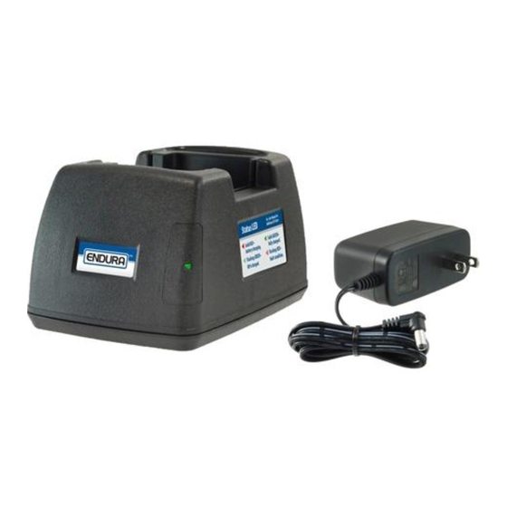
Page 9: Ec1 Features
EC1 Features Status LED information – also see bottom label. Charger base. Charge status LED – illuminates Removable charging pod. green, red, or orange. DC power connection – back of charger. AC to DC power supply (EC1 / EC1-V2 only). -
Page 10: Accessories For In-Vehicle Installation
Accessories For In-Vehicle Installation The items below are included with EC1M and allow the charger to be used in a vehicle. Main mounting bracket. Adjustable tie-down strap – secures battery or radio in charger. Holes for securing main bracket to optional 4-hole AMPS bracket. Holes (2) for securing charger on main bracket with thumb screws (see #10). - Page 11 Accessories For In-Vehicle Installation...
-
Page 12: In-Vehicle Installation (Ec1M)
In-Vehicle Installation (EC1M) Install the charger in an area of the vehicle that is close to a 12V or 24V outlet. The location selected should allow the vehicle power adapter to be connected without excessive stretching of the cable. For a hardwire installation, TWC6M- HW is available. - Page 13 In-Vehicle Installation (EC1M) (continued) Attach the charger to the main bracket as follows: (A) slide the insert nuts into the openings on the base of the charger, (B) place the charger on the main bracket so that the two connection points seat into the openings in the charger base, (C) slide the charger to the right until it is centered, (D) fasten the two thumb screws to the insert nuts to lock the charger to the bracket.
-
Page 14: Charging A Battery
Always use the tie-down strap to secure the radio or battery when your vehicle is in motion. Charging A Battery Confirm that the charging pod and battery are compatible. Connect the charger to power with the power supply (model EC1) or the vehicle power adapter (model EC1M). - Page 15 Charging A Battery (continued) Place the battery to be charged in the charging pod. The battery may also be charged while attached to the radio. When a battery is placed in the charging pod and while charging, the status LED will illuminate RED with no flashing to indicate normal charging.
-
Page 16: Fault Conditions & Advisements
5°C - 40°C (41° F - 104° F) while charging a battery. 10. To prevent battery damage, use EC1-V2 to charge your battery: (A) when the battery is above freezing (0°C / 32° F) or (B) when the battery is not excessively warm to the touch (below 45°C / 113°... - Page 17 Fault Conditions & Advisements (continued) The flash patterns for fault conditions are as follows: LED Pattern Fault Description EC1 / EC1-V2 / EC1M EC1M-V2 Flashes RED Indicates (A) low voltage battery failure or (B) battery has a short circuit. If (A), the battery’s voltage is below the 1 Time •...
- Page 18 Fault Conditions & Advisements (continued) The flash patterns for advisements are as follows: LED Pattern Advisement EC1 / EC1-V2 / EC1M EC1M-V2 Brief reset period for charger after battery is removed. Solid ORANGE • • Allow the LED to go off before inserting another battery.
- Page 19 Fault Conditions & Advisements (continued) EC1 / LED Pattern Advisement EC1-V2 / EC1M EC1M-V2 Flashes ORANGE Battery temperature remains at 0°C (32° F) or below • 1 Time after two hours of monitoring. Remove battery from charger and allow it to warm.
-
Page 20: Warranty And Service
Warranty And Service During Warranty Endura EC chargers are made from high quality materials and designed to provide years of reliable service. The following warranty applies: Power Products Unlimited, Inc. (PPU) warrants this product to be free from defects in workmanship and materials for one-year from date of purchase by the end user. -
Page 21: Specifications
Specifications subject to change without notice. (A) Applies to EC1. Charge rate for EC1-V2 is 700 mA. (B) Complies with FCC Rules, Part 15, Subpart B, Class B 2016, ANSI C63.4:2014. (C) Complies with California Energy Commission CEC-400-2011-005. (D) Complies with U.S. -
Page 22: Accessories (Ec1 / Ec1M)
Accessories (EC1 / EC1M) Part Number Description Information TWC1-PS Power supply. UL listed. Input: 100-240V, 50-60Hz, (Included with EC1 / EC1-V2.) 0.5A. Output: 15.0V, 1.0A. TWC1M-VPA Vehicle power adapter. Length: 20.0” (cord relaxed). (Included with EC1M / EC1M-V2.) Replaceable fuse, 2A. - Page 24 2170 Brandon Trail • Alpharetta, GA 30004 www.powerproducts.com Endura Chargers By Power Products ©2017 Power Products Unlimited, Inc. Power Products, Endura, and Smart-Adaptable-Reliable Smart – Adaptable – Reliable™ are trademarks of Power Products Unlimited, Inc. All rights reserved.
Need help?
Do you have a question about the EC1 and is the answer not in the manual?
Questions and answers