Table of Contents
Advertisement
Quick Links
Specifications
I AMPLIFIER SECTION
FTC OUTPUT POWER both channel driven simultaneously
10% total harmonic distortion (THD)
1 kHz
RMS OUTPUT POWER both channel driven simultaneously
10% total harmonic distortion (THD)
1 kHz
Input Music Port
Sensitivity
Terminal
Output Headphone
Terminal
Output level (CD, 1 kHz, -20 dB)
I TUNER SECTION
FM
Frequency range
Antenna terminals
AM
Frequency range
I CD SECTION
Disc played [8cm (3") or 12cm (5")]
(1) CD-Audio (CD-DA)
2.8 W per channel (6 Ω)
3 W per channel (6 Ω)
100 mv, 15 kΩ
Stereo, 3.5 mm (1/8") jack
Stereo, 3.5 mm (1/8") jack
(16 Ω to 32 Ω)
max. 0.8 mW + 0.8 mW, 32 Ω
87.9 MHz to 107.9 MHz (200 kHz)
87.5 MHz to 108.0 MHz (100 kHz)
75 Ω (unbalanced)
520 kHz to 1710 kHz (10 kHz)
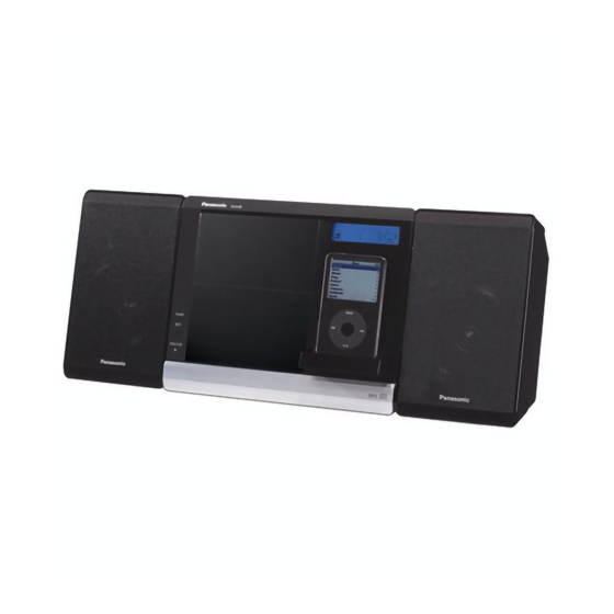
SC-EN38P
SC-EN38PC
Colour
(K)... Black Type
(2) CD-R/RW (CD-DA, MP3)
(3) MP3
Sampling frequency
CD
MP3
Bit rate
MP3
Decoding
Pick up
Wavelength
Laser power
Audio Output (Disc)
Number of channels
Audio performance
Frequency response (CD-Audio)
Wow and flutter
Digital filter
D/A converter
I SPEAKER SECTION
Type
Speaker unit(s)
Full range
Impedance
Input power (IEC)
© 2008 Matsushita Electric Industrial Co. Ltd.. All
rights
reserved.
distribution is a violation of law.
ORDER NO. MD0802019CE
CD Stereo System
44.1 kHz
32 kHz, 44.1 kHz, 48 kHz
32 kbps to 384 kbps
16/20/24 bit linear
CLASS 1
2 channel
20 Hz to 20 kHz
Below measurement limit
MASH (1 bit DAC)
1 Way, 1 speaker system
(Bass reflex)
7 cm (2 3/4") cone type
3 W (MAX)
Unauthorized
copying
A6
785 nm
8
6 Ω
and
Advertisement
Table of Contents

Related Manuals for Panasonic SC-EN38P


Summary of Contents for Panasonic SC-EN38P
- Page 1 ORDER NO. MD0802019CE CD Stereo System SC-EN38P SC-EN38PC Colour (K)... Black Type Specifications I AMPLIFIER SECTION (2) CD-R/RW (CD-DA, MP3) FTC OUTPUT POWER both channel driven simultaneously (3) MP3 10% total harmonic distortion (THD) Sampling frequency 2.8 W per channel (6 Ω) 1 kHz 44.1 kHz...
-
Page 2: Table Of Contents
30 W • Specifications are subject to change without notice. Dimension (W x H X D) 252.5mm x 202.8mm x 133.5 mm I System : SC-EN38P-K Main Unit: SA-EN38P-K (9 15/16” x 7 15/16” x 5 1/4”) Speaker: SB-EN38P-K Mass... -
Page 3: Safety Precautions
SC-EN38P / SC-EN38PC 1 Safety Precautions 1.1. General Guidelines 1. When servicing, observe the original lead dress. If a short circuit is found, replace all parts which have been overheated or damaged by the short circuit. 2. After servicing, ensure that all the protective devices such as insulation barriers, insulation papers shields are properly installed. - Page 4 SC-EN38P / SC-EN38PC 1.2. Before Repair and Adjustment Disconnect AC power, discharge Power Supply Capacitors C501 and C502 through a 10Ω, 1W resistor to ground. DO NOT SHORT-CIRCUIT DIRECTLY (with a screwdriver blade, for instance), as this may destroy solid state devices.
-
Page 5: Prevention Of Electro Static Discharge (Esd) To Electrostatically Sensitive (Es) Devices
SC-EN38P / SC-EN38PC 2 Prevention of Electro Static Discharge (ESD) to Electrostatically Sensitive (ES) Devices Some semiconductor (solid state) devices can be damaged easily by electricity. Such components commonly are called Electrostatically Sensitive (ES) Devices. Examples of typical ES devices are integrated circuits and some field-effect transistors and semiconductor “chip”... -
Page 6: Precaution Of Laser Diode
SC-EN38P / SC-EN38PC 3 Precaution of Laser Diode CAUTION: This unit utilizes a class 1 laser. Invisible laser radiation is emitted from the optical pickup lens. When the unit is turned on: 1. Do not look directly into the pick up lens. -
Page 7: Handling Precautions For Traverse Deck
SC-EN38P / SC-EN38PC 4 Handling Precautions For Traverse Deck The laser diode in the traverse deck (optical pickup) may break down due to potential difference caused by static electricity of clothes or human body. So, be careful of electrostatic breakdown during repair of the traverse deck (optical pickup). -
Page 8: Handling The Lead Free Solder
SC-EN38P / SC-EN38PC 5 Handling the Lead free Solder 5.1. General description about Lead Free Solder (PbF) The lead free solder has been used in the mounting process of all electrical components on the printed circuit boards used for this equipment in considering the globally environmental conservation. -
Page 9: Accessories
SC-EN38P / SC-EN38PC 6 Accessories Note : Refer to Packing Materials & Accessories (Section 21) for part number. Remote control AC cord FM/AM antenna Support stand... -
Page 10: Operation Procedures
SC-EN38P / SC-EN38PC 7 Operation Procedures 7.1. Main Unit & Remote Control Key Buttons Operation... - Page 11 SC-EN38P / SC-EN38PC 7.2. Attach the stand to the unit 7.3. Connection...
- Page 12 SC-EN38P / SC-EN38PC 7.4. External unit...
- Page 13 SC-EN38P / SC-EN38PC 7.5. Disc Information...
-
Page 14: Self Diagnosis And Special Mode Setting
SC-EN38P / SC-EN38PC 8 Self diagnosis and special mode setting This unit is equipped with features of self-diagnostic & special mode setting for checking the functions & reliability. 8.1. Service Mode Summary Table The service mode can be activated by pressing various button combination on the main unit and remote control unit. Below is the... - Page 15 SC-EN38P / SC-EN38PC Item FL Display Key Operation Mode Name Description Front Key Doctor Mode To enter into Doctor Mode for DIsplay 1 In any mode: checking of various items and 1. Press [Volume -] button on main displaying EEPROM and firmware unit follow by [4] and [7] on remote control.
- Page 16 SC-EN38P / SC-EN38PC Item FL Display Key Operation Mode Name Description Front Key Volume Setting To check for the volume setting of the In doctor mode: Mode main unit. The volume will be 1. Press [7] button on remote control.
- Page 17 SC-EN38P / SC-EN38PC Below is the procedures for this mode. Step 1: Enter into Doctor mode (For more information refer to section 8.2 on key operation to enter into this mode). Step 2: When [ ], [1] & [4] are pressed at the doctor mode, the following shall be displayed for 3s. The result shall correspond to the condition met as shown in the table below: 8.3.
-
Page 18: Assembling And Disassembling
SC-EN38P / SC-EN38PC 9 Assembling and Disassembling 9.1. Caution “ATTENTION SERVICER” Some chassis components may be have sharp edges. Be careful when disassembling and servicing. 1. This section describes procedures for checking the operation of the major printed circuit boards and replacing the main components. - Page 19 SC-EN38P / SC-EN38PC 9.2. Disassembly flow chart The following chart is the procedure for disassembling the casing and inside parts for internal inspection when carrying out the servicing. To assemble the unit, reverse the steps shown in the chart below.
- Page 20 SC-EN38P / SC-EN38PC 9.3. Main Parts Location Diagram...
- Page 21 SC-EN38P / SC-EN38PC 9.4. Disassembly of Rear Panel Step 3 : Detach 3P cable at connector (CN601) on Main P.C.B. and remove Rear Panel. Step 1 : Remove 9 screws. Step 2 : Release 6 catches and slightly push the Rear Panel as...
- Page 22 SC-EN38P / SC-EN38PC • Disassembly of AC Inlet P.C.B. 9.5. Disassembly of Transformer P.C.B., AC Inlet P.C.B. & Transformer • Follow the (Step 1) - (Step 3) of item 9.4. • Disassembly of Transformer P.C.B. Step 5 : Release 2 catches and remove AC Inlet P.C.B. as arrow shown.
- Page 23 SC-EN38P / SC-EN38PC • Disassembly of Transformer Caution : During reassembling procedures, ensure the cable are properly dressed. − Follow the (Step 1) - (Step 2) of (Disassembly of Transformer P.C.B.) − Follow the (Step 5) of (Disassembly of AC Inlet P.C.B.) Step 8 : Remove 4 screws.
- Page 24 SC-EN38P / SC-EN38PC 9.6. Disassembly of Tuner P.C.B. 9.7. Disassembly of Main P.C.B. • Follow the (Step 1) - (Step 3) of item 9.4. • Follow the (Step 1) - (Step 3) of item 9.4. • Follow the (Step 1) - (Step 3) of item 9.6.
- Page 25 SC-EN38P / SC-EN38PC 9.8. Replacement of Voltage Regulator IC (IC501) • Follow the (Step 1) - (Step 3) of item 9.4. • Follow the (Step 1) - (Step 3) of item 9.6. • Follow the (Step 1) - (Step 8) of item 9.7.
- Page 26 SC-EN38P / SC-EN38PC 9.8.1. Assembly of Voltage Regulator IC (IC501) Step 3 : Remove Voltage Regulator IC (IC501) from the heatsink unit. Caution : Handle the heatsink unit with caution due to its Step 1 : Apply grease to the heatsink unit.
- Page 27 SC-EN38P / SC-EN38PC 9.9. Replacement of Voltage Regulator IC (IC502) • Follow the (Step 1) - (Step 3) of item 9.4. • Follow the (Step 1) - (Step 3) of item 9.6. • Follow the (Step 1) - (Step 8) of item 9.7.
- Page 28 SC-EN38P / SC-EN38PC 9.9.1. Assembly of Voltage Regulator IC 9.10. Replacement of Voltage (IC502) Regulator Transistor (Q501) • Follow the (Step 1) - (Step 3) of item 9.4. • Follow the (Step 1) - (Step 3) of item 9.6. • Follow the (Step 1) - (Step 8) of item 9.7.
- Page 29 SC-EN38P / SC-EN38PC 9.10.1. Assembly of Voltage Regulator Transistor (Q501) Step 3 : Remove Voltage Regulator Transistor (Q501) from the heatsink unit. Caution : Handle the heatsink unit with caution due to its Step 1 : Apply grease to the heatsink unit.
- Page 30 SC-EN38P / SC-EN38PC 9.11. Replacement of Power AMP IC (IC700) • Follow the (Step 1) - (Step 3) of item 9.4. • Follow the (Step 1) - (Step 3) of item 9.6. • Follow the (Step 1) - (Step 8) of item 9.7.
- Page 31 SC-EN38P / SC-EN38PC 9.11.1. Assembly of Power AMP IC (IC700) 9.12. Replacement of Regulator Transistor (Q502) • Follow the (Step 1) - (Step 3) of item 9.4. • Follow the (Step 1) - (Step 3) of item 9.6. • Follow the (Step 1) - (Step 8) of item 9.7.
- Page 32 SC-EN38P / SC-EN38PC 9.12.1. Assembly of Regulator Transistor (Q502) Step 3 : Remove Regulator Transistor (Q502) from the heatsink unit. Caution : Handle the heatsink unit with caution due to its Step 1 : Apply grease to the heatsink unit.
- Page 33 SC-EN38P / SC-EN38PC 9.13. Disassembly of Tact Switch & Sensor P.C.B. • Follow the (Step 1) - (Step 3) of item 9.4. • Disassembly of Tact Switch P.C.B. Caution : Take extra care for the locator on the Main P.C.B.
- Page 34 SC-EN38P / SC-EN38PC 9.14. Disassembly of CD 9.15. Disassembly of Traverse Mechanism Unit Cover • Follow the (Step 1) - (Step 3) of item 9.4. • Follow the (Step 1) - (Step 3) of item 9.4. • Follow the (Step 1) - (Step 3) of item 9.6.
- Page 35 SC-EN38P / SC-EN38PC 9.16. Disassembly of CD Servo P.C.B. • Follow the (Step 1) - (Step 3) of item 9.4. • Follow the (Step 1) - (Step 3) of item 9.6. • Follow the (Step 1) - (Step 8) of item 9.7.
- Page 36 SC-EN38P / SC-EN38PC 9.17. Disassembly of Motor Unit & Motor P.C.B. • Follow the (Step 1) - (Step 3) of item 9.4. • Follow the (Step 1) - (Step 3) of item 9.6. • Follow the (Step 1) - (Step 8) of item 9.7.
- Page 37 SC-EN38P / SC-EN38PC • Disassembly of Ipod Cradle P.C.B. 9.18. Disassembly of Ipod Cradle P.C.B. • Follow the (Step 1) - (Step 3) of item 9.4. • Follow the (Step 1) - (Step 3) of item 9.6. • Follow the (Step 1) - (Step 8) of item 9.7.
- Page 38 SC-EN38P / SC-EN38PC • Disassembly of LED P.C.B. 9.19. Disassembly of Panel & LED P.C.B. • Follow the (Step 1) - (Step 3) of item 9.4. • Follow the (Step 1) - (Step 3) of item 9.6. • Follow the (Step 1) - (Step 8) of item 9.7.
- Page 39 SC-EN38P / SC-EN38PC 9.20. Disassembly of Detector 9.21. Disassembly of CD Lid P.C.B. • Follow the (Step 1) - (Step 3) of item 9.4. • Follow the (Step 1) - (Step 3) of item 9.6. • Follow the (Step 1) - (Step 3) of item 9.4.
- Page 40 SC-EN38P / SC-EN38PC 9.22. Disassembly of Docking Lid • Follow the (Step 1) - (Step 3) of item 9.4. • Follow the (Step 1) - (Step 3) of item 9.6. • Follow the (Step 1) - (Step 8) of item 9.7.
- Page 41 SC-EN38P / SC-EN38PC 9.23. Disassembly of Function Lid 9.24. Disassembly of Speaker Ass’y • Follow the (Step 1) - (Step 3) of item 9.4. Step 1 : Remove 4 screws. Step 1 : Press and open the Function Lid Ass’y.
- Page 42 SC-EN38P / SC-EN38PC Step 4 : Apply light force to push out the Rear Panel as arrow Step 6 : Remove 2 screws. shown. Step 7 : Remove glue. Caution : Do not exert strong force as it may damage the Step 8 : Remove port unit.
- Page 43 SC-EN38P / SC-EN38PC • Disassembly of Woofer Step 9 : Remove 4 screws. Step 10 : Remove Woofer.
-
Page 44: Service Fixture And Tools
SC-EN38P / SC-EN38PC 10 Service Fixture and Tools Service Tools Remarks Main P.C.B. (CN301) - CD Servo P.C.B. (CN7002) REEX0924 (22 pin FFC cable) [M] (RTL) Main P.C.B. (CN952) - Tact Switch P.C.B. (CN953) REEX0923 (8 pin FFC cable) [M] (RTL) -
Page 45: Service Position
SC-EN38P / SC-EN38PC 11 Service Position Note : For description of the disassembly procedures, see the section 9 11.2. Checking & Repairing Detector 11.1. Checking & Repairing P.C.B Transformer & AC Inlet P.C.B Step 1 : Remove Rear Panel. Step 1 : Remove Rear Panel. - Page 46 SC-EN38P / SC-EN38PC 11.3. Checking & Repairing Tact 11.4. Checking & Repairing Sensor Switch P.C.B P.C.B Step 1 : Remove Rear Panel. Step 1 : Remove Rear Panel. Step 2 : Remove Transformer P.C.B.. Step 2 : Remove Transformer P.C.B..
- Page 47 SC-EN38P / SC-EN38PC 11.5. Checking & Repairing Tuner 11.6. Checking & Repairing Main P.C.B P.C.B Step 1 : Remove Rear Panel. Step 1 : Remove Rear Panel. Step 2 : Remove Transformer P.C.B.. Step 2 : Remove Transformer P.C.B.. Step 3 : Remove Tuner P.C.B..
- Page 48 SC-EN38P / SC-EN38PC Step 9 : Remove 2 screws. Step 10 : Remove Detector P.C.B.. Step 16 : Connect 3P cable at the connector (P651) on Main P.C.B.. Step 17 : Connect 8P cable at the connector (P900) on Main P.C.B..
- Page 49 SC-EN38P / SC-EN38PC 11.7. Checking & Repairing CD 11.8. Checking & Repairing Panel & Servo P.C.B LED P.C.B • Checking Panel P.C.B. Note : Insert CD before Checking CD Servo P.C.B. • Follow (Step 1 - Step 18) of item 10.6 •...
- Page 50 SC-EN38P / SC-EN38PC 11.9. Checking & Repairing Ipod Cradle P.C.B • Follow (Step 1 - Step 18) of item 10.6 Step 19 : Remove 2 screws. Step 20 : Check Ipod Cradle P.C.B..
-
Page 51: Voltage Measurement & Waveform Chart
STANDBY Ref No. IC7001 MODE CD PLAY STANDBY Ref No. IC7001 MODE CD PLAY STANDBY Ref No. IC7002 MODE CD PLAY STANDBY Ref No. IC7002 MODE CD PLAY STANDBY Ref No. Q7601 MODE CD PLAY STANDBY SC-EN38P/PC CD SERVO P.C.B. - Page 52 SC-EN38P / SC-EN38PC 12.1.2. Main P.C.B. Ref No. IC200 MODE CD PLAY 4.32 4.32 4.32 4.34 4.34 4.33 4.33 4.34 4.33 4.33 4.34 4.34 4.34 4.34 4.34 3.43 3.43 STANDBY 0.33 0.33 0.33 0.33 0.33 0.33 0.33 0.33 0.33 0.22 0.33 0.33 0.33 0.33 0.33...
- Page 53 SC-EN38P / SC-EN38PC Ref No. Q301 Q380 Q381 Q382 Q502 MODE CD PLAY 3.33 3.34 3.37 0.19 0.19 14.1 9.08 14.1 STANDBY 3.43 3.37 0.28 0.29 0.04 0.07 Ref No. Q504 Q505 Q508 Q509 Q510 MODE CD PLAY 7.56 5.19 6.95 4.45 6.95 4.01...
- Page 54 SC-EN38P / SC-EN38PC 12.1.6. Transformer P.C.B. Ref No. Q7601 MODE CD PLAY 0.25 STANDBY 0.27 SC-EN38P/PC TRANSFORMER P.C.B. 12.1.7. Tuner P.C.B. Ref No. MODE CD PLAY STANDBY Ref No. MODE CD PLAY STANDBY Ref No. MODE CD PLAY STANDBY SC-EN38P/PC TUNER P.C.B.
-
Page 55: Wiring Connection Diagram
SC-EN38P / SC-EN38PC 13 Wiring Connection Diagram JW601 CD SERVO P.C.B TRANSFORMER P.C.B CN7002 SENSOR P.C.B SOLDER SIDE AC INLET P.C.B Z950 JW951* CAUTION RISK OF ELECTRIC SHOCK JK600 AC VOLTAGE LINE. SOLDER SIDE PLEASE DO NOT TOUCH THIS P.C.B... - Page 56 SC-EN38P / SC-EN38PC...
-
Page 57: Block Diagram
SC-EN38P / SC-EN38PC 14 Block Diagram 14.1. CD SERVO BLOCK DIAGRAM "<!&-%>#<&-BC<# ;9$&-"'=C-!"8# >%;98# ;!%!# -'.//)# -'0/,# D.3/,# >%;98# -'.//)# -'0/,# <"E98#=8&79# -'.//)# -'0/,# $>=# !"#$%&'# ()*)+# $->B# -'.//)# -'0/,# $=%!%# -'.//)# -'0/,# <A"!"#=9!9-!"8# H.)/,# 35# 3.# 32# 1,# 10# 1)# 14# 89F"'#... - Page 58 SC-EN38P / SC-EN38PC 14.2. TUNER / USB / D PORT BLOCK DIAGRAM :$#%'!# %$#%'!# <,# >1,# >.# -',# -'01/# !"#$%&'()*)+# ;E&!-A# 6>"-B#=&%F8%$# -',# -'01/# >"C!# !"#$%&'(,*)+# -',# -'01/# 6>"-B#=&%F8%$# &-,# 8"C!# -,66////,,)/# -',# -'01/# ="# !C'98#&-# -:,# -',# -'01/# !"#$%&'()*)+# 6>"-B#=&%F8%$#...
- Page 59 SC-EN38P / SC-EN38PC 14.3. MAIN (1/2) / TRANSFORMER BLOCK DIAGRAM &-)//# &-.//# -,%6////)221# -,6%/////0.)# %C=&"#;"C'=#<8"-9;;"8# <"E98#%$<# -',# -'01/# 8Q&'# >-A# !C?8# 8?"C!# >Q"C!# TB51/# :8"$#!C'98# A9%=<A"'9# -',# -'01/# 6>"-B#=&%F8%$# !C?># >Q&'# 8Q"C!# 8-A# >?"C!# -'.//)# -'0/,# -=?8# D.)/# TB3/)# (D.4/+# ;<9%B98#...
- Page 60 SC-EN38P / SC-EN38PC 14.4. MAIN (2/2) / PANEL /SENSOR / SWITCH / TACT SWITCH / SWITCH / MOTOR BLOCK DIAGRAM <%'9># &-2/,# $',/,9:,3BHE# U5//# $&-8"<8"-9;;"8# >-=#=&;<>%L# ,?4# 1?02# A%>!# A%>!# <-"'!Q<"E# <-"'!# <-"'!Q=<# 01?02# ,?04# <-"'!Q=<# D82/4# <5//# TE5//# >-=Q&'A# &'A#...
-
Page 61: Notes Of Schematic Diagram
SC-EN38P / SC-EN38PC 15 Notes Of Schematic Diagram (All schematic diagrams may be modified at any time with the development of new technology) Notes: S650: CD Top switch. S651: CD Bottom switch. S950: Power switch. (Power S951: CD Open/Close. (CD Open/Close S952: Vol-. - Page 62 SC-EN38P / SC-EN38PC...
-
Page 63: Schematic Diagram
SC-EN38P / SC-EN38PC 16 Schematic Diagram 16.1. CD SERVO CIRCUIT ;-A9$# % # ! &-#=&%F8%$#?## , # #-=#;9# 8 # 7 "#-&8-C&# ! # #"<!&-%# > # # <&-BC# < # # -&8-C&# ! # \#@#6#;&F'%# > # # >&'# 9 # \#-=?=%# # ;&F'%# >... - Page 64 SC-EN38P / SC-EN38PC 16.2. TUNER CIRCUIT ;-A9$%# ! &-#=&%F8%$#?#)# #!C'98#-&8-C&!# !>3 \#@#6#;&F'%># # >&'9# \:$#;&F'%>#>&'9# \%$#;&F'%>#>&'9# \%$*:$#;&F'%>#>&'9# 8)5# 8,0# 0P0B# 80,# 4P.B# -4)# -44# >.# ,1/<# -)0# /P/))# F)6<-/////,.# ,/B# 3P07,//# -,4# 4./<# 802# 805# 0P0B# ,//B# -40# /P/4.# 6/-=%6////,5#...
- Page 65 SC-EN38P / SC-EN38PC 16.3. MAIN CIRCUIT ;-A9$%!&-#=&%F8%$?0# #$%&'#-&8-C&!# \#@6#;&F'%>#>&'9# \#$%&'#;&F'%>#>&'9# \#&<"=#%C=&"#;&F'%>#>&'9# \#:$*%$#;&F'%>#>&'9# \#$C;&-#<"8!#;&F'%>#>&'9# $C!9Q6# %FQ=%!%# -'01/# <>>Q-9# %FQ->B# <>>Q-9# <>>Q=&# <>>Q=&# <>>Q->B# <>>Q->B# &-.//# <>>Q="# -,6%/////0.)# <>>Q="# F'=# 8.//# !"# <"E98#%$<#&-# !CQF'=# )P)B# !C'98#-&8-C&!# =0P07# =0P07# (-',+#&'## !C'Q8# !C'Q8-A# ;-A9$%!&-# !C'Q>#...
- Page 66 SC-EN38P / SC-EN38PC ;-A9$%!&-#=&%F8%$?4# &# &# #$%&'#-&8-C&!# \#@6#;&F'%>#>&'9# \#$C;&-#<"8!#;&F'%>#>&'9# \#&<"=#%C=&"#;&F'%>#>&'9# -'2/,# ;!6L0P07# <5//# =17# "-=Q;=%# >9=Q7--# :"8#;":!E%89# 7;;# 789:?# >9=QF'=# ="E'>"%=&'F# "-=Q;-># >-=Q&'A# !"# >-=Q&'A# '8;!# >-=Q-9# <%'9>#-&8-C&!## >-=Q-9# (TE5//+#&'## $$"="# >-=Q->B# >-=Q-># ;-A9$%!&-# 8223# 82.)# >-=Q=&# >-=Q=&# 2)/# 4P.B# 82..#...
- Page 67 SC-EN38P / SC-EN38PC ;-A9$%!&-#=&%F8%$?1# #$%&'#-&8-C&!# \#@6#;&F'%>#>&'9# \#-=#;&F'%>#>&'9# %&# -'0/,# -=Q># &<"=Q17# %F'=# F'=# =1,.# -0/0# =<"8!Q17# 6/%--B/////1# -=Q>Ya# ,///d# -=Q8# %F'=# &-1/,#?#&-1/)# -=Q8Ya# >0/)# D1/,# -0/4# F/%)//=////)# >0/)# =0P07# -/=%ULL///,.# =F'=# ,///d# 7YOZ[# F'=# 6,6%-F////42# 7">!%F9#89FC>%!"8#&-# ;!Q&'# D0/,# 7">!%F9#89FC>%!"8# =-=9!# ;!Q->B#...
- Page 68 SC-EN38P / SC-EN38PC 16.4. PANEL CIRCUIT, LED CIRCUIT, DETECTOR CIRCUIT and MOTOR CIRCUIT ;-A9$%!&-#=&%F8%$?3# #<%'9>#-&8-C&!# #>9=#-&8-C&!# \#@6#;&F'%>#>&'9# =554#?#=551# 855/# 855,# U5//# 6/6%38,////0# >1%-%LL///))# :>#=&;<>%L# -55,# -55/# =55/# =554# =55)# =55,# ,37,W# ,37,W# 60%9%/////12# 855)# =55,# ,)# ,0# ,5# )/# ),# ))# )0# )3# ).# )2#...
- Page 69 SC-EN38P / SC-EN38PC 16.5. IPOD CRADLE CIRCUIT ;-A9$%!&-#=&%F8%$#?#.# #&<"=#-8%=>9#-&8-C&!# \#@6#;&F'%>#>&'9# \#&<"=#%C=&"#;&F'%>#>&'9# \#C;6#;&F'%>#>&'9# -',//0# >,/,)# T/TA-/////04# =F'=# =F'=# <-#;L'-# D,//. 76C;# <;E)# >,/,4# 6,%=$=/////, =4:6,8,////5# T/TA-/////04# 7">!%F9#89FC>%!"8 -A%;;&;QF'=# 8,/,.# -',//,# :E#F'=# D8,//3 :E#F'=# 6,F6-:TT//44 :E#!<%@# >,//0# T/TA-////,/.# ;E&!-A C;6Q=@# :E#!<%#?# >,//4# T/TA-////,/.#...
- Page 70 SC-EN38P / SC-EN38PC 16.6. TACT SWITCH CIRCUIT, SENSOR CIRCUIT, TRANSFORMER CIRCUIT and AC INLET CIRCUIT ;-A9$%!&-#=&%F8%$?2# #!%-!#;E&!-A#-&8-C&!# #;9';"8#-&8-C&!# \#@6#;&F'%>#>&'9# \#$C;&-#<"8!#;&F'%>#>&'9# 851,# 851)# 8510# 8514# 8511# 8513# 851.# 8512# 851/# )P)B# )P.B# 0P5B# 1P3B# 2P)B# ,1B# 00B# 2)B# ,P1B# TE51,g# ;51)# ;510#...
-
Page 71: Printed Circuit Board
SC-EN38P / SC-EN38PC 17 Printed Circuit Board 17.1. CD Servo P.C.B. and Tuner P.C.B. TUNER P.C.B. (REPX0652A) CD SERVO P.C.B (REPV0111A) TP51 (RF) C7227 R31 C44 W7014 C7204 W7015 C7226 R7212 TP18 TP50 C7228 TP17 R7218 C7216 C7230 TP13 R7221... - Page 72 SC-EN38P / SC-EN38PC 17.2. Main P.C.B. MAIN P.C.B. (REPX0652A) Q301 C303 C304 CN301 C305 W528 W303 R309 W530 W311 R310 C856 R307 L302 W507 W287 CN952 W288 C207 W289 CN381 R827 R835 W290 R823 R821 W226 W291 L381 Q380 R833...
- Page 73 SC-EN38P / SC-EN38PC 17.3. Panel P.C.B., Led P.C.B., Detector P.C.B., IPOD Cradle P.C.B. and Tact Switch P.C.B. PANEL P.C.B. (REPX0652A) LED P.C.B. (REPX0652A) JW990* Z900 R991 C991 12 13 D994 D992 C905 C904 R907 0581A 0581A C906 W900 C903 C902...
- Page 74 SC-EN38P / SC-EN38PC 17.4. Sensor P.C.B., Motor P.C.B., Transformer P.C.B. and AC Inlet P.C.B. TRANSFORMER P.C.B. (REPX0652A) SENSOR P.C.B. (REPX0652A) JW951* Z950 S951 R950 S950 (CD OPEN/ CLOSE) (POWER) 0581A 0581A SENSOR W601 C605 C603 D603 R601 I L J Q600 MOTOR P.C.B.
-
Page 75: Illustration Of Ic's, Transistors And Diodes
SC-EN38P / SC-EN38PC 18 Illustration of IC’s, Transistors and Diodes 0HBA0000238 (48P) 1BB00001120 (36P) 0GAE0000007 BA5948FPE2 1BA00000372 0DAZYY00017 MN6627954MA (100P) 1AB00002885 (52P) MN101EF16KXW (100P) No.1 0 B B 00090 B1BAAJ000003 B1ABDF000026 UNR511100L B1A ND000003 B1B G000002 B1ABGD000022 UNR521300L B1AD F000001... -
Page 76: Terminal Function Of Ic's
SC-EN38P / SC-EN38PC 19 Terminal Function of IC’s 19.1. IC801 (MN101EF16KXW) MICROPROCESSOR Pin No. Mark Function Pin No. Mark Function PCONT_POW Power Control Output N.C. No connection (PWR Sply Active HIGH) N.C. No connection PCONT_DP 5.3V Regulator Control N.C. No connection N.C. -
Page 77: Exploded Views
SC-EN38P / SC-EN38PC 20 Exploded Views 20.1. Cabinet Parts Location... - Page 78 SC-EN38P / SC-EN38PC...
- Page 79 SC-EN38P / SC-EN38PC 20.2. Packaging...
- Page 80 SC-EN38P / SC-EN38PC...
-
Page 81: Replacement Parts List
SC-EN38P / SC-EN38PC 21 Replacement Parts List Notes: • Important safety notice: Components identified by mark have special characteristics important for safety. Furthermore, special parts which have purposes of fire-retardent (resistors), high-quality sound (capacitors), low noise (resistors), etc are used. - Page 82 SC-EN38P / SC-EN38PC Ref. Part No. Part Name & Description Remarks Ref. Part No. Part Name & Description Remarks PCB9 REPX0652A PANEL P.C.B (RTL) B0CDAD000010 DIODE PCB10 REPX0652A LED P.C.B B0CDAB000019 DIODE (RTL) B0CDAB000019 DIODE PCB11 REPX0652A MOTOR P.C.B B0AACK000004...
- Page 83 SC-EN38P / SC-EN38PC Ref. Part No. Part Name & Description Remarks Ref. Part No. Part Name & Description Remarks G2BPC0000017 COIL L740 D0GBR00JA008 0 1/16W G0C101KA0029 INDUCTOR L951 D0GBR00JA008 0 1/16W G2A390C00001 COIL L953 D0GBR00JA008 0 1/16W L302 G0A200D00002 CHOKE COIL...
- Page 84 SC-EN38P / SC-EN38PC Ref. Part No. Part Name & Description Remarks Ref. Part No. Part Name & Description Remarks R380 D0GB155JA007 1.5M 1/10W PACKING MATERIALS R381 D0GB125JA007 1.2M 1/10W R382 D0GB224JA007 220K 1/10W RPGX1891-2 PACKING CASE [M] P R383 D0GB224JA007...
- Page 85 SC-EN38P / SC-EN38PC Ref. Part No. Part Name & Description Remarks Ref. Part No. Part Name & Description Remarks R823 D0GB102JA008 1K 1/16W R960 D0GB471JA008 470 1/16W R824 D0GB102JA008 1K 1/16W R961 ERJ8GEY0R00V 0 1/4W R825 D0GB102JA008 1K 1/16W R962...
- Page 86 SC-EN38P / SC-EN38PC Ref. Part No. Part Name & Description Remarks Ref. Part No. Part Name & Description Remarks ECJ1VB1C183K 0.018uF 16V C507 ECA0JAK101XB 100uF 6.3V F1H1E103A029 0.01uF 25V C508 F1K1A1060017 10uF 10V ECJ1VB1C183K 0.018uF 16V C511 F2A1A101A159 100uF 10V...
- Page 87 SC-EN38P / SC-EN38PC Ref. Part No. Part Name & Description Remarks C1001 ECJ1VB1H104K 0.1uF 50V C1002 ECJ1VB1H104K 0.1uF 50V C1003 ECJ1VB1H104K 0.1uF 50V C1004 ECJ1VB1H104K 0.1uF 50V C1004 ECJ1VB1H104K 0.1uF 50V C7107 ECJ1VB1H223K 0.022uF 50V C7142 ECJ1VB1H332K 3300pF 50V C7154 ECJ1VB1C104K 0.1uF 16V...
Need help?
Do you have a question about the SC-EN38P and is the answer not in the manual?
Questions and answers