Table of Contents
Advertisement
Quick Links
Specifications
n AMPLIFIER SECTION
FTC OUTPUT POWER both channel driven simultaneously
10% total harmonic distortion (THD)
1 kHz
RMS OUTPUT POWER both channel driven simultaneously
10% total harmonic distortion (THD)
1 kHz
Output impedance
HEADPHONE
MUSIC PORT
Phone Jack
Terminal
Music Port Jack
Terminal
n TUNER SECTION
Frequency range
FM
AM
n CD SECTION
Disc played [8cm (3") or 12cm (5")]
(1) CD-Audio (CD-DA)
(2) CD-R/RW (CD-DA, MP3)
(3) MP3
1.8 W per channel
2 W per channel
16 W to 32 W
14 kW
3.5 mm stereo
3.5 mm stereo
87.9 MHz to 107.9 MHz (200 kHz)
87.5 MHz to 108.0 MHz (100 kHz)
520 kHz to 1710 kHz (10 kHz)
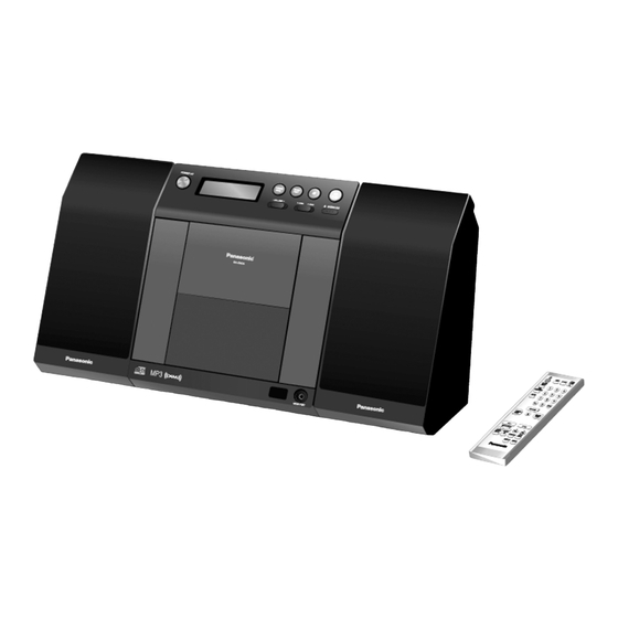
SC-EN33PC
Colour
(S)... Silver Type
System
SC-EN33PC-S
Main Unit: SA-EN33PC-S
Speakers: SB-EN33APC-S (L) & SB-EN33PC-S (R)
Sampling frequency
CD
MP3
Bit rate
MP3
Decoding
Pick up
Wavelength
Laser power
Audio Output (Disc)
Number of channels
Frequency response
Wow and flutter
Digital filter
D/A converter
n GENERAL
Power supply
Power consumption
Dimension (W x H X D)
Mass
With speakers
Without speakers
n SPEAKER SECTION
© 2007 Matsushita Electric Industrial Co. Ltd.. All
rights
reserved.
distribution is a violation of law.
ORDER NO. MD0703020CE
CD Stereo System
44.1 kHz
32 kHz, 44.1 kHz, 48 kHz
32 kbps to 384 kbps
16/20/24 bit linear
CLASS 1
2 channel
20 Hz to 20 kHz (+1, -2 dB)
Below measurement limit
MASH (1 bit DAC)
AC 120 V, 60 Hz
220mm x 236mm x 146 mm
(8 21/32" x 9 9/32" x 5 3/4")
3.57 kg (7.87 lbs)
1.27 kg (2.80 lbs)
Unauthorized
copying
A6
785 nm
8
30 W
and
Advertisement
Table of Contents

Subscribe to Our Youtube Channel
Related Manuals for Panasonic SC-EN33PC


Summary of Contents for Panasonic SC-EN33PC
- Page 1 ORDER NO. MD0703020CE CD Stereo System SC-EN33PC Colour (S)... Silver Type System SC-EN33PC-S Main Unit: SA-EN33PC-S Speakers: SB-EN33APC-S (L) & SB-EN33PC-S (R) Specifications n AMPLIFIER SECTION Sampling frequency FTC OUTPUT POWER both channel driven simultaneously 44.1 kHz 10% total harmonic distortion (THD) 32 kHz, 44.1 kHz, 48 kHz...
-
Page 2: Table Of Contents
SC-EN33PC Type 1 Way, 1 speaker system Power consumption in standby mode: Speaker(s) 8 cm (5 1/2”) cone type 6 W 2.0 W (appx.) Impedance Notes: · Specifications are subject to change without notice. Input power 6 (MAX) Dimension (W x H x D) 121 mm x 236 mm x 146 mm ·... - Page 3 SC-EN33PC 19.1. IC801 (MN101EF16ZXW) Servo Processor,Digital Signal 20.1. Cabinet Parts Location Processor/Digital filter and D/A Converter 20.2. Packaging 20 Exploded Views 21 Replacement Parts List...
-
Page 4: Safety Precautions
SC-EN33PC 1 Safety Precautions 1.1. General Guidelines 1. When servicing, observe the original lead dress. If a short circuit is found, replace all parts which have been overheated or damaged by the short circuit. 2. After servicing, ensure that all the protective devices such as insulation barriers and insulation papers shields are properly installed. -
Page 5: Caution For Fuse Replacement
SC-EN33PC 1.2. Caution for fuse replacement 1.3. Before repair and adjustment Disconnect AC power, discharge Power Capacitors C611 and C616 through a 10W , 1W resistor to ground. DO NOT SHORT-CIRCUIT DIRECTLY (with a screwdriver blade, for instance), as this may destroy solid state devices. -
Page 6: Prevention Of Electro Static Discharge (Esd) To Electrostatically Sensitive (Es) Devices
SC-EN33PC 2 Prevention of Electro Static Discharge (ESD) to Electrostatically Sensitive (ES) Devices Some semiconductor (solid state) devices can be damaged easily by electricity. Such components commonly are called Electrostatically Sensitive (ES) Devices. Examples of typical ES devices are integrated circuits and some field-effect transistors and semiconductor “chip”... -
Page 7: Precaution Of Laser Diode
SC-EN33PC 3 Precaution of laser diode CAUTION: This unit utilizes a class 1 laser diode in the optical pickup unit . Invisible laser radiation is emitted from the optical pickup lens. Wavelength: 780nm When the unit is turned on: 1. Do not look directly into the optical pickup lens. - Page 8 SC-EN33PC Caution : The static electricity of your clothes will not be grounded through the wrist strap. So, take care not to let your clothes touch the traverse deck (optical pickup). Caution when replacing the Traverse Deck The traverse deck has a short point shorted with solder to protect the laser diode against electrostatics breakdown. Be sure to...
-
Page 9: About Lead Free Solder (Pbf)
SC-EN33PC 5 About Lead Free Solder (PbF) 5.1. Service caution based on legal restrictions 5.1.1. General description about Lead Free Solder (PbF) The lead free solder has been used in the mounting process of all electrical components on the printed circuit boards used for this equipment in considering the globally environmental conservation. -
Page 10: Accessories
SC-EN33PC 6 Accessories Remote Control AC Cord FM/AM Antenna... -
Page 11: Operation Procedures
SC-EN33PC 7 Operation Procedures 7.1. Remote Control Key Buttons Operations 7.2. Main Unit Key Buttons Operations... -
Page 12: Connection
SC-EN33PC 7.3. Connection... -
Page 13: Self Diagnosis And Special Mode Setting
SC-EN33PC 8 Self diagnosis and special mode setting This unit is equipped with features of self-diagnostic & special mode setting for checking the functions & reliability. 8.1. Service Mode Summary Table The service mode can be activated by pressing various button combination on the main unit and remote control unit. Below is the... - Page 14 SC-EN33PC Item FL Display Key Operation Mode Name Description Front Key Doctor Mode To enter into Doctor Mode for DIsplay 1 In any mode: checking of various items and 1. Press [ ] button on main unit displaying EEPROM and firmware follow by [4] and [7] on remote version.
- Page 15 SC-EN33PC Item FL Display Key Operation Mode Name Description Front Key Volume Setting To check for the volume setting of the In doctor mode: Mode main unit. The volume will be 1. Press [7] button on remote control. automatically set to its respective level (in dB).
-
Page 16: Error Code Table
SC-EN33PC Below is the procedures for this mode. Step 1: Enter into Doctor mode (For more information refer to section 8.2 on key operation to enter into this mode). Step 2: When [ ], [1] & [4] are pressed at the doctor mode, the following shall be displayed for 3s. The result shall correspond to the condition met as shown in the table below: 8.3. -
Page 17: Assembling And Disassembling
SC-EN33PC 9 Assembling and Disassembling 9.1. Caution “ATTENTION SERVICER” Some chassis components may have sharp edges. Be careful when disassembling and servicing. 1. This section describes procedures for checking the operation of the major printed circuit boards and replacing the main components. -
Page 18: Disassembly Flow Chart
SC-EN33PC 9.2. Disassembly flow chart The following chart is the procedure for disassembling the casing and inside parts for internal inspection when carrying out the servicing. To assemble the unit, reverse the steps shown in the chart as below. 9.2.1. -
Page 19: Main Components & P.c.b. Locations
SC-EN33PC 9.3. Main Components & P.C.B. Locations 9.3.1. Main Parts Locations 9.3.2. Speaker Unit Parts Location (For SB-EN33A only) -
Page 20: Disassembly Of Rear Cabinet
SC-EN33PC 9.4. Disassembly of Rear Cabinet Step 1 Remove 10 screws. Step 3 Detach cable (FP806) on Main P.C.B. and remove the rear cabinet as arrow shown. Step 2 Lift up the rear cabinet. 9.5. Disassembly of Panel P.C.B. & LED P.C.B. -
Page 21: Disassembly Of Switch P.c.b. And Traverse Unit
SC-EN33PC Step 2 Detach cables (P352, P351 ,FP701 ,P801 & P802) on Main P.C.B.. Step 3 Lift up the Main P.C.B. Sensor P.C.B. and Tuner P.C.B. 9.7. Disassembly of Switch P.C.B. and Traverse Unit · Follow the (Step 1) - (Step 3) of Item 9.4 - Disassembly of Rear Cabinet ·... -
Page 22: Replacement Of Traverse Cover
SC-EN33PC Step 4 Release 6 catches to remove Power P.C.B. & Tact Switch P.C.B.. · Assemble of Front Ornament into slot. Step 3 Release 1 claw to remove front ornament. Ensure front ornament fully insert to front cabinet. 9.9. Replacement of Traverse Cover ·... -
Page 23: Disassembly Of Cd Servo P.c.b
SC-EN33PC Caution: Keep the floating springs (x 4) in safe place & avoid losing them. 9.10. Disassembly of CD Servo P.C.B. · Follow the (Step 1) - (Step 3) of Item 9.4 - Disassembly of Rear Cabinet · Follow the (Step 1) - (Step 2) of Item 9.6 - Disassembly of Main P.C.B. , Sensor P.C.B. & Tuner P.C.B. -
Page 24: Disassembly Of Cd Block & Cd Lid
SC-EN33PC Step 4 Remove the belt. Step 5 Remove pulley gear, 2nd gear and drive gear. Step 6 Remove 2 screws at motor unit. Step 7 Remove 1 screw and unsolder 3 points at gear base. · Disassembly of motor assembly (gears & belt) Step 2 Remove motor assembly. -
Page 25: Disassembly Of Speakers
SC-EN33PC Step 3 Remove 4 screws, remove sw lever (left) and roller guide (R). Step 2 Remove 2 screws. Step 4 Remove cd lid. 9.13. Disassembly of Speakers 9.13.1. Disassembly of the speaker (SB-EN33) - (R) Step 1 Remove 6 screws. - Page 26 SC-EN33PC Step 4 Remove 4 screws. · Disassembly of net frame ass’y Step 5 Remove 4 screws. Step 2 Remove the back cabinet ass’y.. Step 3 Unsolder the lead wires, silver (-) and gold (+).
- Page 27 SC-EN33PC 9.13.2. Disassembly of the rear cabinet (SB-EN33A) - (L) Step 1 Remove 6 screws. · Disassembly of net frame ass’y Step 5 Remove 4 screws. Step 2 Remove the back cabinet ass’y.. Step 3 Unsolder the lead wires. Step 4 Remove 4 screws.
- Page 28 SC-EN33PC · Removal of Transformer P.C.B. Step 1 Remove 1 screw on back cabinet assy. Step 2 Remove 3 screws to remove the port unit. Step 3 Remove 4 screws on Transformer P.C.B. unit. Step 4 Unsolder wire and remove Transformer P.C.B..
-
Page 29: Service Fixture And Tools
SC-EN33PC 10 Service Fixture and Tools Service Tools Extension FFC (A) CD Servo P.C.B. - Main P.C.B. REEX0485 (14 Pins) 11 Service Positions General proceduree: Connect the DC in cord cable from (SB-EN33A) to main set, connect AC power supply cord to speaker to on the set. Load in cd and switch off the set. -
Page 30: Check And Repair Of Cd Servo P.c.b
SC-EN33PC 11.1. Check and Repair of CD Servo P.C.B. -
Page 31: Check And Repair Of Main P.c.b., Sensor P.c.b., Tuner
SC-EN33PC 11.2. Check and repair of Main P.C.B., Sensor P.C.B., Tuner P.C.B., Motor P.C.B., Panel P.C.B., LED P.C.B., Power Switch P.C.B., Tact Switch P.C.B. & Switch P.C.B. -
Page 32: Voltage And Waveform Chart
SC-EN33PC 12 Voltage and Waveform Chart Note: Circuit voltage and waveform described herein shall be regarded as reference information when probing defect point, because it may differ from an actual measuring value due to difference of Measuring instrument and its measuring condition and product itself. -
Page 33: Cd Servo P.c.b
SC-EN33PC 12.2. CD Servo P.C.B. 12.3. Motor P.C.B. 12.4. Panel P.C.B. 12.5. Tuner P.C.B. -
Page 34: Waveform Chart
SC-EN33PC 12.6. Waveform Chart... -
Page 35: Wiring Connection Diagram
SC-EN33PC 13 Wiring Connection Diagram... - Page 36 SC-EN33PC...
-
Page 37: Block Diagram
SC-EN33PC 14 Block Diagram 14.1. CD Servo... -
Page 38: Tuner
SC-EN33PC 14.2. Tuner... -
Page 39: Main (1/2), Transformer & Sensor
SC-EN33PC 14.3. Main (1/2), Transformer & Sensor... -
Page 40: Main (2/2), Panel, Led, Power Switch, Tact Switch, Switch
SC-EN33PC 14.4. Main (2/2), Panel, LED, Power Switch, Tact Switch, Switch & Motor... -
Page 41: Notes Of Schematic Diagrams
SC-EN33PC 15 Notes of Schematic Diagrams (All schematic diagrams may be modified at any time with the development of the new technology) S351 : CD TOP Switch S352 : CD BOTTOM Switch S801 : POWER Switch ( S802 : VOL - Switch (... - Page 42 SC-EN33PC...
-
Page 43: Schematic Diagram
SC-EN33PC 16 Schematic Diagram (All schematic diagrams may be modified at any time with the development of the new technology) -
Page 44: A) Cd Servo Circuit
SC-EN33PC 16.1. (A) CD Servo Circuit... -
Page 45: B) Tuner Circuit
SC-EN33PC 16.2. (B) Tuner Circuit... -
Page 46: C) Main Circuit
SC-EN33PC 16.3. (C) Main Circuit... - Page 47 SC-EN33PC...
- Page 48 SC-EN33PC...
-
Page 49: D) Panel Circuit, (E) Led Circuit, (F) Power Switch Circuit, (G) Tact Switch Circuit & (H) Switch Circuit
SC-EN33PC 16.4. (D) Panel Circuit, (E) LED Circuit, (F) Power Switch Circuit, (G) Tact Switch Circuit & (H) Switch Circuit... -
Page 50: Circuit
SC-EN33PC 16.5. (I) Motor Circuit, (J) Sensor Circuit & (K) Transformer Circuit... -
Page 51: Printed Circuit Board
SC-EN33PC 17 Printed Circuit Board Note: Circuit board diagrams may be modified at any time with the development of new technology. -
Page 52: A) Cd Servo P.c.b. & (B) Tuner
SC-EN33PC 17.1. (A) CD Servo P.C.B. & (B) Tuner P.C.B. -
Page 53: C) Main
SC-EN33PC 17.2. (C) Main P.C.B. -
Page 54: D) Panel P.c.b., (E) Led P.c.b., (F) Power Switch
SC-EN33PC 17.3. (D) Panel P.C.B., (E) LED P.C.B., (F) Power Switch P.C.B., (G) Tact Switch P.C.B., (H) Switch P.C.B., (I) Motor P.C.B., (J) Sensor P.C.B. & (K) Transformer P.C.B. -
Page 55: Illustration Of Ics, Transistors And Diodes
SC-EN33PC 18 Illustration of ICs, Transistors and Diodes C0HBA0000238 (48P) C1BB00000732 (32P) C0GAE0000007 C0AAAA000036 BA5948FPE2 B1BCCG000002 MN101EF16ZXW (100P) C1BB00001120 (36P) MN6627954MA (100P) No.1 B1ABDF000026 B0ACCE000003 MAZ80560ML B1BAAJ000003 B1ACND000003 B1ABGD000022 B1ADCF000001 Cathode Cathode B1ADCF000063 B1GBCFGJ0016 UNR511100L UNR521300L Anode Anode UNR521400L B0CDAB000019... -
Page 56: Terminal Function Of Ic's
SC-EN33PC 19 Terminal Function of IC's 19.1. IC801 (MN101EF16ZXW) Servo Processor,Digital Signal Processor/Digital filter and D/A Converter Pin No. Mark Function Pin No. Mark Function PCONT1 Power Control Output N.C. No connection (PWR Sply Active N.C. No connection HIGH) PLL_DO... -
Page 57: Cabinet Parts Location
SC-EN33PC 20 Exploded Views 20.1. Cabinet Parts Location... - Page 58 SC-EN33PC...
-
Page 59: Packaging
SC-EN33PC 20.2. Packaging... - Page 60 SC-EN33PC...
-
Page 61: Replacement Parts List
SC-EN33PC 21 Replacement Parts List Notes: · Important safety notice: Components identified by mark have special characteristics important for safety. Furthermore, special parts which have purposes of fire-retardent (resistors), high-quality sound (capacitors), low noise (resistors), etc are used. When replacing any of these components, be sure to use only manufacturer’s specified parts shown in the parts list. - Page 62 SC-EN33PC Ref. No. Part No. Part Name & Description Remarks Ref. No. Part No. Part Name & Description Remarks REPV0116F SWITCH P.C.B. [M](RTL) D803 B0ACCE000003 DIODE REPV0116F MOTOR P.C.B. [M](RTL) D901 B0EAMM000038 DIODE REPV0116F SENSOR P.C.B. [M](RTL) D902 B0EAMM000038 DIODE REPV0116F TRANSFORMER P.C.B.
- Page 63 SC-EN33PC Ref. No. Part No. Part Name & Description Remarks Ref. No. Part No. Part Name & Description Remarks L1002 J0JBC0000019 CHIP INDUCTOR W731 ERJ3GEY0R00V CHIP JUMPER W735 ERJ6GEY0R00V CHIP JUMPER LB7262 D0GBR00JA008 CHIP JUMPER W736 ERJ3GEY0R00V CHIP JUMPER LB7263...
- Page 64 SC-EN33PC Ref. No. Part No. Part Name & Description Remarks Ref. No. Part No. Part Name & Description Remarks A1-1 RKK-HTR0283H R/C BATTERY COVER R216 D0GB473JA008 47K 1/16W K2CB2CB00018 AC CORD R217 D0GB562JA008 5.6K 1/16W RQTV0162-P O/I BOOK (En) R301...
- Page 65 SC-EN33PC Ref. No. Part No. Part Name & Description Remarks Ref. No. Part No. Part Name & Description Remarks R814 D0GB102JA008 1K 1/16W R7332 D0GB102JA008 1K 1/16W R815 D0GB102JA008 1K 1/16W R7335 ERJ3GEYJ101V 100 1/16W R816 D0GB102JA008 1K 1/16W R7336...
- Page 66 SC-EN33PC Ref. No. Part No. Part Name & Description Remarks Ref. No. Part No. Part Name & Description Remarks C113 ECJ1VB1C224K 0.22 16V C807 ECJ1VC1H560J 56P 50V C114 ECJ1VB1C473K 0.047 16V C808 ECJ1VC1H560J 56P 50V C115 ECJ1VB1C105K 1 16V C809...
- Page 67 SC-EN33PC Ref. No. Part No. Part Name & Description Remarks C7338 ECJ1VB1C563K 0.056 16V C7339 ECJ1VB1C183K 0.018 16V C7352 ECJ1VB1C183K 0.018 16V C7601 ECEA0JKA330I 33 6.3V C7613 ECJ1VB1C104K 0.1 16V C7614 F2A0J101A198 100 6.3V C7626 ECJ1VB1C104K 0.1 16V C7670 ECJ1VB1C104K 0.1 16V...
Need help?
Do you have a question about the SC-EN33PC and is the answer not in the manual?
Questions and answers