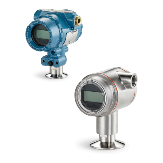
Emerson Rosemount 3051HT Quick Start Manual
Hygienic pressure transmitter with foundation fieldbus protocol
Hide thumbs
Also See for Rosemount 3051HT:
- Quick start manual (28 pages) ,
- Quick start manual (28 pages) ,
- Quick start manual (24 pages)

Related Manuals for Emerson Rosemount 3051HT


Summary of Contents for Emerson Rosemount 3051HT
- Page 1 Quick Start Guide 00825-0200-4091, Rev CA June 2020 ™ Rosemount 3051HT Hygienic Pressure Transmitter ™ with F Fieldbus Protocol OUNDATION...
- Page 2 Quick Start Guide June 2020 NOTICE This guide provides basic guidelines for the Rosemount 3051HT Transmitter. It does not provide instructions for configuration, diagnostics, maintenance, service, troubleshooting, Explosion-proof, Flameproof, or intrinsically safe (I.S.) installations. WARNING Explosions could result in death or serious injury.
- Page 3 DD4: DD Rev 1 FieldCommGroup.org Emerson.com 00809-0100-47 74, Rev CA DD5: DD Rev 1 FieldCommGroup.org newer Emerson AMS Device Manager V Emerson.com 10.5 or higher: DD Rev 2 Emerson AMS Device Manager V Emerson.com 8 to 10.5: DD Rev 1...
- Page 4 Transmitter must not be securely mounted or clamped in place when changing transmitter orientation. Conduit entry orientation When installing a Rosemount 3051HT, it is recommended installing so a conduit entry faces downward or parallel to the ground to maximize drainability when cleaning.
- Page 5 June 2020 Quick Start Guide Figure 2-2: In-line Protected Gage Vent Low Side Pressure Port Aluminum Polished 316 SST A. Low side pressure port (atmospheric reference) Clamping When installing clamp, follow recommended torque values provided by gasket manufacturer. Note To maintain performance, torquing a 1.5-in. Tri Clamp beyond 50 in-lb. is not recommended on pressure ranges below 20 psi.
- Page 6 PHYSICAL DEVICE TAG A. Device revision Note The device description loaded in the host system must be at the same revision as this device. The device description can be downloaded from the host system website, from Emerson.com/Rosemount, or from FieldCommGroup.org. Emerson.com/Rosemount...
- Page 7 June 2020 Quick Start Guide The security and simulate switches The security and simulate switches are located on the electronics. Figure 2-4: Transmitter Electronics Board Aluminum Polished 316 SST A. Simulate switch B. Security switch 2.3.1 Setting the security switch The security switch allows ( ) or prevents ( ) any configuration of the transmitter.
- Page 8 Use copper wire of sufficient size to ensure the voltage across the transmitter power terminals does not drop below 9 Vdc. A minimum of 12 Vdc under normal operating conditions is recommended. Shielded twisted pair Type A cable is recommended. Emerson.com/Rosemount...
- Page 9 June 2020 Quick Start Guide • Power supply voltage can be variable, especially under abnormal conditions such as when operating on battery backup. Procedure 1. To power the transmitter, connect the power leads to the terminals indicated on the terminal block label. Note The Rosemount 3051 power terminals are polarity insensitive, which means the electrical polarity of the power leads does not matter...
- Page 10 Continuously connect the cable shields to the power supply ground. c) Connect the cable shields for the entire segment to a single good earth ground at the power supply. Emerson.com/Rosemount...
- Page 11 4. Plug and seal unused conduit connections. Note The Rosemount 3051HT polished 316 SST housing only provides ground termination inside the terminal compartment. Power supply The transmitter requires between 9 and 32 Vdc (9 and 30 Vdc for intrinsic safety) to operate and provide complete functionality.
- Page 12 DeltaV Explorer for the resource and transducer blocks and Control Studio for the function blocks. 2.5.1 Configure the AI block Navigation instructions for each step are provided in the Figure 2-7. In addition, the screens used for each step are shown in the Figure 2-6. Emerson.com/Rosemount...
- Page 13 June 2020 Quick Start Guide Figure 2-6: Basic Configuration Menu Tree (Calibration) (Overview) Primary Value Pressure Sensor Trim Calibration Sensor Limits Device Information Restore Factory Calibration Locate Device Last Calibration Points Scale Gauges Calibration Details (Device Information) (Materials of Construction) Identification ( 1 ) Sensor Revisions...
- Page 14 This may be elevated or suppressed for level applications. c) Enter the XD_SCALE 100% point. This may be elevated or suppressed for level applications. d) If the L_TYPE is Direct, guided setup automatically places the AI block into AUTO mode to return the device to service. Emerson.com/Rosemount...
- Page 15 June 2020 Quick Start Guide 4. If the L_TYPE selected is Indirect or Indirect Square Root, set OUT_SCALE to change engineering units. a) Select OUT_SCALE UNITS from the menu. b) Set the OUT_SCALE low value. This may be elevated or suppressed for level applications. c) Set the OUT_SCALE high value.
- Page 16 Channel 2 is the sensor temperature. ™ If the F Fieldbus Diagnostics Suite Option Code D01 is enabled, OUNDATION these additional channels are available. • Channel 12 is the SPM mean. • Channel 13 is the SPM standard deviation. Emerson.com/Rosemount...
- Page 17 June 2020 Quick Start Guide To configure SPM, refer to the Rosemount 3051 F Fieldbus OUNDATION Reference Manual. Procedure 1. Select AI Block Unit Setup. 2. Place the AI Block in Out of Service mode. 3. Select the signal conditioning L_TYPE from the menu. •...
- Page 18 The simulate enable/disable switch may be in either position for normal device operation. 2.5.5 Enable software write lock Procedure 1. Navigate from the Overview screen. a) Select Device Information. b) Select the Security and Simulation tab. 2. Perform Write Lock Setup to enable software write lock. Emerson.com/Rosemount...
- Page 19 June 2020 Quick Start Guide 2.5.6 AI block configuration parameters Use the pressure example for a guide. Parameters Enter data Channel 1 = Pressure, 2 = Sensor temp, 12 = SPM mean, 13 = SPM standard deviation L_Type Direct, indirect, or square root XD_Scale Scale and engineering units torr at 0 °C...
- Page 20 1. Navigate to Configure → Guided Setup. 2. Select Zero Trim. The method will execute the zero trim. Manual Setup 3. Navigate to Overview → Calibration → Sensor Trim. 4. Select Zero Trim. The method will execute the zero trim. Emerson.com/Rosemount...
- Page 21 A copy of the EU Declaration of Conformity can be found at the end of the Quick Start Guide. The most recent revision of the EU Declaration of Conformity can be found at Emerson.com. Ordinary Location Certification As standard, the transmitter has been examined and tested to determine...
- Page 22 2. The enclosure may be made of aluminum alloy and given a protective polyurethane paint finish; however care should be taken to protect it from impact or abrasion if located in Zone 0. International I7 IECEx Intrinsic Safety Certificate: IECEx BAS 09.0076X Standards: IEC 60079-0:2011, IEC 60079-11:2011 Emerson.com/Rosemount...
- Page 23 June 2020 Quick Start Guide ™ Markings: HART : Ex ia IIC T5/T4 Ga, T5(–20 °C ≤ T ≤ +40 °C), T4(–20 °C ≤ T ≤ +70 °C) ® PROFIBUS : Ex ia IIC T4 (–20 °C ≤ T ≤ +60 °C) Parameter PROFIBUS Voltage U...
- Page 24 EPL Ga. Additional certifications ® All Rosemount 3051HT transmitters with the following connections are 3-A approved and labeled: T32: 1½-in. Tri Clamp T42: 2-in. Tri Clamp...
- Page 25 June 2020 Quick Start Guide Figure 3-1: Rosemount 3051HT Declaration of Conformity Quick Start Guide...
- Page 26 Quick Start Guide June 2020 Figure 3-2: Rosemount 3051HT Declaration of Conformity Emerson.com/Rosemount...
- Page 27 June 2020 Quick Start Guide Figure 3-3: Rosemount 3051HT Declaration of Conformity Quick Start Guide...
- Page 28 Quick Start Guide June 2020 China RoHS Emerson.com/Rosemount...
- Page 29 June 2020 Quick Start Guide Quick Start Guide...
- Page 30 Quick Start Guide June 2020 Emerson.com/Rosemount...
- Page 31 June 2020 Quick Start Guide Quick Start Guide...
- Page 32 The Emerson logo is a Twitter.com/Rosemount_News trademark and service mark of Emerson Electric Facebook.com/Rosemount Co. Rosemount is a mark of one of the Emerson Youtube.com/user/ family of companies. All other marks are the RosemountMeasurement property of their respective owners.
Need help?
Do you have a question about the Rosemount 3051HT and is the answer not in the manual?
Questions and answers