
Related Manuals for SHOWTEC Pinspot Bar 4 RGBW


Summary of Contents for SHOWTEC Pinspot Bar 4 RGBW
- Page 1 USER MANUAL ENGLISH Pinspot Bar 4 RGBW Product code: 30295 Highlite International B.V. – Vestastraat 2 – 6468 EX – Kerkrade – the Netherlands...
- Page 2 Pinspot Bar 4 RGBW Preface Thank you for purchasing this Showtec product. The purpose of this user manual is to provide instructions for the correct and safe use of this product. Keep the user manual for future reference as it is an integral part of the product. The user manual shall be stored at an easily accessible location.
-
Page 3: Table Of Contents
Pinspot Bar 4 RGBW Table of contents Introduction ................................4 Before Using the Product ..........................4 Intended Use ............................... 4 Product Lifespan ..............................4 LEDs Lifespan ............................... 4 Text Conventions ..............................4 Symbols and Signal Words ..........................5 Symbols on the Information Label ........................5 Safety .................................. - Page 4 Pinspot Bar 4 RGBW Curves Select ............................28 Dimmer Speed ............................29 Pixel Dir ..............................29 DMX Fail ..............................30 DMX Sync .............................30 Lock ...............................30 Factory ..............................31 Information ..............................31 DMX Channels ..............................32 4 Channels, 5 Channels, 6 Channels, 10 Channels ................32 8 Channels ..............................33 16 Channels, 19 Channels ........................34...
-
Page 5: Introduction
After unpacking, check the contents of the box. If any parts are missing or damaged, contact your Highlite International dealer. Your shipment includes: ● Showtec Pinspot Bar 4 RGBW ● 2 x safety eye ● 1 x spigot ●... -
Page 6: Symbols And Signal Words
Pinspot Bar 4 RGBW ● References: References to chapters and parts of the device are in bold lettering, for example: “Refer to 2. Safety”, “turn the adjustment screw (02)” ● 0–255: Defines a range of values ● Notes: Note: (in bold lettering) is followed by useful information or tips Symbols and Signal Words Safety notes and warnings are indicated throughout the user manual by safety signs. -
Page 7: Safety
Pinspot Bar 4 RGBW Safety Important Read and follow the instructions in this user manual before installing, operating or servicing this product. The manufacturer will not accept liability for any resulting damages caused by the non-observance of this manual. Warnings and Safety Instructions... - Page 8 Pinspot Bar 4 RGBW WARNING Risk of burns due to hot surface The surface and the inner parts of the device can become very hot during operation. ● Do not touch the device during operation. ● Allow the device to cool down for at least 15 minutes before handling.
-
Page 9: Requirements For The User
Pinspot Bar 4 RGBW ● If the device is exposed to extreme temperature variations (e.g. after transportation), do not switch it on immediately. Let the device reach room temperature before switching it on, otherwise it may be damaged by the formed condensation. -
Page 10: Description Of The Device
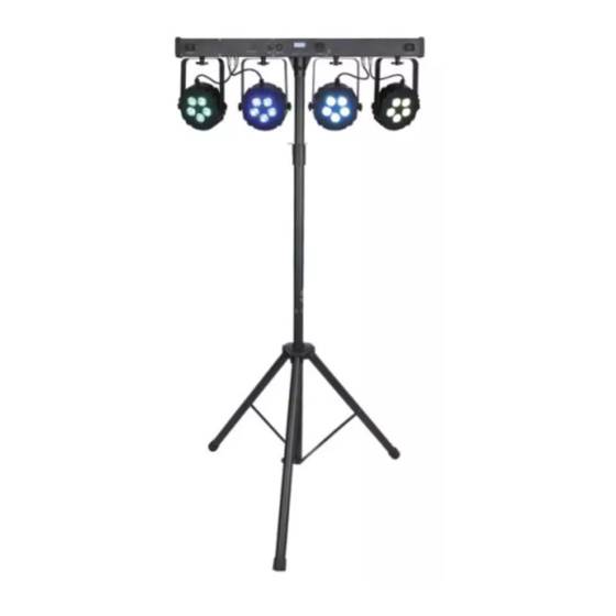
Description of the Device The Pinspot Bar 4 RGBW is a high-output bar with 4 pin spots. The T-bar is lightweight which makes it ideal for many different events and purposes. The optional 20° beam shapers make the bar suitable for highlighting buffets, displaying products or pointing out tables. -
Page 11: Back View
Pinspot Bar 4 RGBW Back View Fig. 03 05) Pro power connector (Blue) IN 06) Ground/earth connection 07) Fuse 5S1,5A/250 V 08) Control panel: OLED display and control buttons 09) 3-pin DMX signal connector IN 10) 5-pin DMX signal connector IN... -
Page 12: Product Specifications
Pinspot Bar 4 RGBW Product Specifications Model: Pinspot Bar 4 RGBW Electrical: Input voltage: 100–240 V AC, 50/60 Hz Power consumption: 90 W Fuse: 5S1,5A/250 V Physical: Dimensions: 800 x 177 x 278 mm (LxWxH) Weight: 6,5 kg Optics: Light source:... -
Page 13: Optional Accessories
Pinspot Bar 4 RGBW Optional Accessories You can additionally purchase the following accessories: Product code: 30297 (20° Beamshaper for Pinspot Bar 4 RGBW & WW) Product code: 70912 (Lighting stand Alu, including spigot adapter) Dimensions Fig. 05 Product code: 30295... -
Page 14: Installation
Pinspot Bar 4 RGBW Installation Safety Instructions for Installation WARNING Incorrect installation can cause serious injuries and damage of property. If trussing systems are used, installation must be carried out only by instructed or skilled persons. Follow all applicable European, national and local safety regulations concerning rigging and trussing. - Page 15 Pinspot Bar 4 RGBW To mount the device, follow the steps below: 01) Use the included quick-lock brackets to attach the device to the supporting structure, as shown in Fig. 06. Make sure that the device cannot move freely. Optionally, you can install the device on a lighting stand, as shown in Fig.
-
Page 16: Angle Adjustment
Pinspot Bar 4 RGBW Angle Adjustment You can adjust the angle of the device with the adjustment screws (15). 01) Turn the adjustment screws (15) counterclockwise to release them. 02) Tilt the device to the desired angle (see Fig. 08). -
Page 17: Connecting To Power Supply
Pinspot Bar 4 RGBW Connecting to Power Supply DANGER Electric shock caused by short-circuit The device accepts AC mains power at 100–240 V and 50/60 Hz. Do not supply power at any other voltage or frequency to the device. This device falls under IEC protection class I. Make sure that the device is always electrically connected to the ground (earth). -
Page 18: Setup
Disconnect power supply before connecting or disconnecting data cables. Stand-alone Setup When the Pinspot Bar 4 RGBW is not connected to a controller or to other devices, it functions as a stand- alone device. It can be operated manually or in auto mode. -
Page 19: Dmx Cables
Fig. 10. Fig. 10 Master/Slave Setup The Pinspot Bar 4 RGBW supports master/slave control mode. To connect multiple devices in master/slave setup, follow the steps below: 01) Connect the first device’s DMX OUT connector to the second device’s DMX IN connector. -
Page 20: Dmx Linking
04) Continue assigning the starting addresses of the remaining devices by adding each time 19 to the previous number. Make sure that you do not have any overlapping channels in order to control each Pinspot Bar 4 RGBW correctly. If two or more devices are addressed similarly, they will work similarly. -
Page 21: Operation
Before connecting the device to the power supply, make sure that the current, voltage and frequency match the input voltage, current and frequency specified on the information label on the device. Control Modes The Pinspot Bar 4 RGBW supports the following control modes: ● Stand-alone: Manual, Auto, Program ●... -
Page 22: Control Panel
Pinspot Bar 4 RGBW Control Panel A) OLED display DOWN button C) UP button D) SETUP button MODE button Fig. 13 ● Use the MODE button to exit the current submenu and to return to the Main Menu. ● Use the UP/DOWN buttons to navigate through the menus or to increase/decrease numeric values. -
Page 23: Menu Overview
Pinspot Bar 4 RGBW Menu Overview Product code: 30295... - Page 24 Pinspot Bar 4 RGBW Product code: 30295...
-
Page 25: Main Menu Options
Pinspot Bar 4 RGBW Main Menu Options Upon start-up, the display will show the current software version and the temperature. The main menu has the following options: Press the UP/DOWN buttons to navigate through the main menu. 02) Press the SETUP button to open the submenus. -
Page 26: Address
Pinspot Bar 4 RGBW Address In this menu you can set the desired DMX starting address. Press the UP/DOWN buttons to set the desired DMX address. The adjustment range is 001–512. Press the SETUP button to confirm your choice. Channels In this menu you can set the desired DMX channel mode. -
Page 27: Auto
Pinspot Bar 4 RGBW Auto In this menu you can set Auto mode. While in the main menu, press the UP/DOWN buttons to choose AUTO. Press the SETUP button to enter the menu. The display will show: Press the UP/DOWN buttons to choose YES (to start the auto show) or NO (to return to the previous screen. -
Page 28: Programs 02-23
Pinspot Bar 4 RGBW Program 01 If you have chosen program 01, the display will show: Press the UP/DOWN buttons to choose one of the 2 options: ● COLOR ● STROBE Press the SETUP button to enter the desired menu. -
Page 29: Settings
Pinspot Bar 4 RGBW Settings In this menu you can adjust the device’s settings. While in the main menu, press the UP/DOWN buttons to choose SETTINGS. Press the SETUP button to enter the menu. The display will show: Press the UP/DOWN buttons to choose one of the 7 submenus: ●... -
Page 30: Dimmer Speed
Pinspot Bar 4 RGBW Dimmer Speed In this menu you can set the dimmer speed. Press the UP/DOWN buttons to select FAST or SMOOTH. Press the SETUP button to confirm your choice. Pixel Dir In this menu you can set the pixel direction. -
Page 31: Dmx Fail
Pinspot Bar 4 RGBW DMX Fail In this menu you can set the device’s behavior in case of a DMX failure. Press the UP/DOWN buttons to select one of the 4 options: ● OFF: the device will black out the light output ●... -
Page 32: Factory
Pinspot Bar 4 RGBW Factory In this menu you can restore the default factory settings. Press the UP/DOWN buttons to select YES or NO. Press the SETUP button to confirm your choice. Information In this menu you can view the device’s current software version, temperature, total lifetime and the device’s UID number. -
Page 33: Dmx Channels
Pinspot Bar 4 RGBW DMX Channels 4 Channels, 5 Channels, 6 Channels, 10 Channels 4 CH 5 CH 6 CH 10 CH Function Value Setting Master Dimmer 000–255 From low to high intensity (0–100 %) 000–010 No function Linear Strobe 011–255... -
Page 34: Channels
Pinspot Bar 4 RGBW 4 CH 5 CH 6 CH 10 CH Function Value Setting 077–087 Program 7 088–098 Program 8 099–109 Program 9 110–120 Program 10 121–131 Program 11 132–142 Program 12 143–153 Program 13 154–164 Program 14 165–175 Program 15 176–186... -
Page 35: 16 Channels, 19 Channels
Pinspot Bar 4 RGBW 16 Channels, 19 Channels 16 CH 19 CH Function Value Setting Master 000–255 From low to high intensity (0–100 %) Dimmer 000–010 No function Linear Strobe 011–255 From low to high frequency (0–20 Hz) 000–010 No function FX Strobe 011–255... -
Page 36: Troubleshooting
Pinspot Bar 4 RGBW Troubleshooting This troubleshooting guide contains solutions to problems which can be carried out by an ordinary person. The device does not contain user-serviceable parts. Unauthorized modifications to the device will render the warranty void. Such modifications may result in injuries and material damage. -
Page 37: Maintenance
Pinspot Bar 4 RGBW Maintenance Safety Instructions for Maintenance DANGER Electric shock caused by dangerous voltage inside Disconnect power supply before servicing or cleaning. WARNING Risk of burns due to hot surface Allow the device to cool down for at least 15 minutes before servicing or cleaning. -
Page 38: Basic Cleaning Instructions
Pinspot Bar 4 RGBW Basic Cleaning Instructions The external lens of the device must be cleaned periodically in order to optimize the light output. The cleaning schedule depends on the conditions at the site where the device is installed. When smoke or fog machines are used at the site, the device will need more frequent cleaning. -
Page 39: Deinstallation, Transportation And Storage
Pinspot Bar 4 RGBW Deinstallation, Transportation and Storage Instructions for Deinstallation WARNING Incorrect deinstallation can cause serious injuries and damage of property. ● Let the device cool down before dismounting. ● Disconnect power supply before deinstallation. ● Always observe the national and site-specific regulations during deinstallation and derigging of the device. - Page 40 ©2020 Showtec...
Need help?
Do you have a question about the Pinspot Bar 4 RGBW and is the answer not in the manual?
Questions and answers