Kramer FC-28 Quick Start Manual
Hide thumbs
Also See for FC-28:
- User manual (68 pages) ,
- User manual (79 pages) ,
- User manual (65 pages)
Advertisement
Scan for full manual
Step 1: Check what's in the box
FC-28 Ethernet Controller
1 IR cable (C-A35M/RE-10)
Step 2: Get to know your FC-28
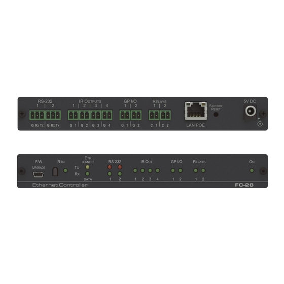
Front Panel
#
Feature
1
F/W UPGRADE Mini USB Connector
2
IR IN Sensor
3
ETH LEDs
CONNECT
DATA
4
RS-232 LEDs
TX 1
RX 1
TX 2
RX 2
5
IR OUT 1 ~ 4 LEDs
6
I/O 1 ~ 2 LEDs
7
RELAY 1 ~ 2 LEDs
8
ON LED
Rear Pane
#
Feature
1
RS-232 Two 3-pin
Terminal Blocks
2
IR 1 ~ 4 Four 2-pin Terminal Blocks
3
I/O Two 2-pin
Terminal Blocks
4
RELAY Two 2-pin
Terminal Blocks
5
LAN POE RJ-45 Connector
6
RESET Button
7
5V DC Connector
FC-28 Quick Start
FC-28 Quick Start Guide
This guide helps you install and use your
Go to
www.kramerav.com/downloads/FC-28
upgrades are available.
Function
Connect to a PC to perform a firmware upgrade
Sensor for IR learning
Lights orange when the Ethernet port is connected
Flashes green when data is transferred over the Ethernet link
Lights green when data Is transmitted on serial port 1
Lights red when data is received on serial port 1
Lights green when data Is transmitted on serial port 2
Lights red when data is received on serial port 2
The associated LED lights green when the relevant IR port transmits data.
Note: When IR learning is in progress, the relevant IR Out LED lights and the
for normal operation
Lights green when the port is triggered
Lights green when the relay is closed
Lights green when the unit is on
Function
1
Connect to the first RS-232 controlled device
2
Connect to the second RS-232 controlled device
Connect to IR blasters/emitters using cables up to 80m (260ft) long
1
Connect to sensors or devices to be controlled, (for example, a motion sensor). Port may be
configured as a digital input, digital output, or analog input
2
Connect to the second sensor or device to be controlled
1
Connect to the first device to be controlled by relay, (for example, a motorized projection screen)
2
Connect to the second device to be controlled by relay
Connect to a PC or other controller directly or via a LAN
Press and hold while power-cycling the device to reset to factory default parameters
Connect to the 5V DC power supply, center pin positive. External power supply is not needed when
the device is supplied power by a PoE provider
FC-28
for the first time.
to download the latest user manual and check if firmware
1 Bracket set
1 Power supply 5V DC
P/N: 2 9 0 0 - 3 0 1 2 7 9 QS
4 Rubber feet
1 Quick start guide
FC-28
is unavailable
Rev: 3
Advertisement
Table of Contents

Related Manuals for Kramer FC-28


Summary of Contents for Kramer FC-28
- Page 1 1 Bracket set 4 Rubber feet 1 IR cable (C-A35M/RE-10) 1 Power supply 5V DC 1 Quick start guide Step 2: Get to know your FC-28 Front Panel Feature Function F/W UPGRADE Mini USB Connector Connect to a PC to perform a firmware upgrade...
- Page 2 FC-28 in order to connect to it. This can be done by using K-LAN Configurator to discover the IP address of the FC-28. This is available for download from our website at www.kramerav.com. Web pages; upon taking the device out of the box, use the default host name “FC-26-xxxx”, where...
Need help?
Do you have a question about the FC-28 and is the answer not in the manual?
Questions and answers