Table of Contents
Advertisement
Quick Links
Advertisement
Table of Contents

Related Manuals for Parker HMR 08 Series


Summary of Contents for Parker HMR 08 Series
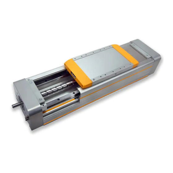
- Page 1 Modular Electric HMR Linear Drives Assembly and Operating Instructions...
- Page 2 Parker-Hannifin GmbH shall not be held liable, regardless of any legal basis, except for cases of intent or gross negligence; injuries to life, body or health; or defects of malicious nondisclosure or whose absence was expressly guaranteed in writing.
-
Page 3: Table Of Contents
Contents Section Page Foreword to the Operating Instructions Safety Product Information Scope of Application Type Plate Application, Proper Use Prerequisite for Product Usage Conversions and Modifications Spare Parts and Accessories Transportation and Storage Transportation Storage Brief Description and Function General Setup and Mode of Action Profile versions and Carrier Profile versions... -
Page 4: Foreword To The Operating Instructions
Operators Operators for the overall system must ensure that the HMR is only operated by authorized and qualified personnel. Authorized personnel include trained specialists from the operator, from the manufacturer (Parker-Hannifin GmbH) and from an approved service partner. Working in a safety-conscious manner Check at reasonable intervals that personnel are working in a safety-conscious manner and adhering to the operating instructions. -
Page 5: Product Information
Product Information Designs Ball screw drive Belt drive Linear motor Scope of Application The description in these operating instructions relates to the products. 3.1.1 Ball Screw Drive Linear drive with ball screw drive and parallel guide HMRS08 HMRS11 HMRS15 HMRS18 HMRS24 3.1.2 Belt Drive Linear drive with toothed belt and parallel guide... -
Page 6: Application, Proper Use
Conversions and Modifications HMR linear drives may not be modified with respect to the design or safety-related features without the written approval of Parker-Hannifin GmbH. Any unauthorized modification in this respect will exclude any liability on the part of Parker-Hannifin GmbH. -
Page 7: Transportation And Storage
These must therefore be avoided! • Attach ropes as shown/use fork as shown. NOTE Notify the shipping company and Parker-Hannifin GmbH or the delivery company immediately, in writing, of any transportation damage or missing parts. Storage The storage location must be: •... -
Page 8: Brief Description And Function
Modular Electric HMR Linear Drives Brief Description and Function General The HMR catalog contains extensive information on the following: • Dimensions, space requirements • Load-carrying capacity, forces and torques • Weights and further technical data The electric linear drives from the HMR series may only be operated within the permissible specifications. We reserve the right to make technical changes. - Page 9 6.3.1 HMRS Ball Screw Drive A carriage is linearly moved by a rotating ball screw drive driven by the motor; the carriage is mounted on a guide system in a movable manner. The screw turns clockwise. The load to be moved is fastened onto the carriage. The permissible thrust force, speed and the linear displacement per rotation of the drive shaft depends on the design of the screw used.
- Page 10 Modular Electric HMR Linear Drives 6.3.2 HMRB Belt Drive A carriage is linearly moved by a toothed belt driven by the motor; the carriage is mounted on a guide system in a movable manner. The load to be moved is fastened onto the carriage. The permissible thrust force, speed and the lead constant per rotation of the drive shaft depends on the design and on the toothed belt used.
-
Page 11: Profile Versions
Ball bearing guide Runner blocks with balls are moved linearly on a precision guide rail made of steel. The maintenance schedule recommended by Parker Hannifin in section 9 must be followed. Carriage The carriage moves an externally connected load in a linear fashion. The external load may only be fastened at the pre-existing threaded holes. -
Page 12: Assembly
(max) The sum of all loads must under no circumstance be > 1. Take note of the additional information in the Parker HMR catalogue on the “Maximum permissible load” on page 7. Electrical information ► The controller, motor, position detection and all other necessary electrical elements must be connected according to technical rules, within the responsibility of the operator. -
Page 13: Installation Of Linear Drive
Installation of Linear Drive All installation measurements can be found under “6.3 Carrier profile and drive body” on page 8 and in the HMR catalogue. ► During assembly, the HMR must be sufficiently supported and securely placed in a machine/system. ATTENTION Straightness tolerance exceeded The screw-on surface is important! - Page 14 Modular Electric HMR Linear Drives 7.2.2 Mounting with T-slot fixture ► Use of the side T-slot profile. Screwing direction downwards. Clamps can be supplied as accessories, see Parker HMR catalogue from page 38. NOTE ► Adhere to the tightening torques for screws according to section 7.1 on page 12.
- Page 15 7.2.3 Distance between supports Distance between supports FY permissible distance between supports [mm] Distance between supports Fz permissible Distance between supports [mm]...
-
Page 16: Attaching The Payload
Modular Electric HMR Linear Drives Attaching the Payload The user is responsible for the use of the HMR and makes decisions on the attachment of loads as well as the operating status with speed, acceleration and frequency of movements. The HMR may only be installed according to the catalog’s specifications. -
Page 17: Cover For Ip54
Cover for IP54 It is also possible to install various assemblies and equipment as a retrofit. When doing so, remove the cover as necessary. HMRS Clamping plate Cover sheet outer band Carriage cover Outer band Inner strip guide A-coil with sealing Sealing band band Lateral... - Page 18 Modular Electric HMR Linear Drives For HMR installation, maintenance purposes or conversion: 7.4.1 IP54 Cover Disassembly Cover sheet Clamping plate Carriage cover outer band Outer band HMRB ► Remove the clamping plate of the outer band on the end caps. ►...
- Page 19 7.4.2 IP54 Cover Assembly The cover can be retrofitted; refer to section 11.1. on page 45. The following instructions also apply to retrofitting, converting or maintaining the HMR. For information on necessary disassembly, refer to section 7.4.1 on page 18. ATTENTION It is possible to implement an incorrect assembly sequence.
- Page 20 Modular Electric HMR Linear Drives Mount the wipers and outer band Lateral Clamping plate Outer band wiper outer band Outer band coating Holder cover HMRB ► Insert the lateral wipers into the grooves on the carriage. Pay attention to the alignment (lips should be facing outward). ►...
-
Page 21: Position Detection With Magnetic Switches
Position Detection with Magnetic Switches ATTENTION Potential damage to equipment! Missing or incorrect signals from the end position switches in the controller. ► Essentially, clamp and set up end switches before commissioning! 7.5.1 Definition End position switch The use of end position switches is highly recommended for operating electric linear drives to prevent mechanical damage in the end positions. - Page 22 Modular Electric HMR Linear Drives 7.5.2 Magnetic Switch Types Electrical connection: cable Electrical connection: cable Electrical connection: plug type RST-K type EST-K type RST-S Reed 2-pole Reed 2-pole PNP 3-pole Closing function Closing function brown (bn) + / - (normally open) (normally open) blue (bl) AC / DC...
- Page 23 7.5.5 Setting up the Internal Magnetic Switches The IP54 cover must be opened as per section 7.4.1 on page 18. Tip: Adjust the carriage to the desired position (end position/homing) and then move the magnetic switch in the T-slot until the switch point is reached. End switch E + HMRB End switch E -...
- Page 24 Modular Electric HMR Linear Drives 7.5.6 Setting up the External Magnetic Switches Only possible with the IP54 cover! Retrofitting: All magnetic switches are mounted via a switch rail to be affixed onto the IP54 cover. Terminal profile switch groove End switch E + Homing switch R T-slot cable holder End switch E -...
-
Page 25: Impact Protection
Impact Protection Impact protection reduces the risk of mechanical damage from an unbraked, unforeseeable impact in the end position. If the safety distance of the end positions is crossed by the carriage and payload, the shock absorbers compensate, in full or in part, for the residual energy. The shock absorbers are only intended to protect a foreseeable impact of the carriage in the mechanical end position and not for continuous operation. -
Page 26: Motor And Gearbox Mounting
Modular Electric HMR Linear Drives Motor and Gearbox Mounting Overview / exploded view of motor installation with a flange plate, using a toothed belt as an example. Motor coupling Motor Drive shaft Coupling housing Motor flange Overview / exploded view of gearbox installation with two flange plates, using a spindle drive as an example. - Page 27 Parker-Hannifin or the operator. EL-sizing, the software-based design program from Parker-Hannifin, also provides reliable combinations of linear drive and drive system. The maximum torque on the drive shaft of the linear drive must not be exceeded at any time.
- Page 28 Modular Electric HMR Linear Drives 7.7.3 Drive System Installation NOTE When installed, both parts of the motor coupling must have a defined gap dimension “Y”. Also note the clearance dimensions in the following table in relation to the shaft of the motor or gearbox used. Motor dimensions [mm] max.
- Page 29 ► Mount the motor coupling with clearance “Z” to Motor Coupling the motor shaft or gearbox shaft Gearbox (see table page 27). WARNING Shaft breakage due to NON-alignment Severe injuries and damage to property caused by unbraked payload. ► Centering of drive shaft and motor shaft/gearbox shaft via coupling housing and flange.
-
Page 30: Commissioning
Modular Electric HMR Linear Drives Commissioning The HMR linear drive can generate quick linear movements with great force. This can result in injuries due to crushing of body parts or damage caused by collision with other system parts if the safety regulations are not observed. An EMERGENCY STOP device must be available. -
Page 31: Maintenance And Repair
Maintenance and Repair Customer Service To obtain the address for spare parts and customer service, see the back of these operating instructions. General Cleaning Maintenance and repair work may only be carried out by trained personnel CAUTION Crushing hazard due to unexpected movements This could result in severe injuries or damage to property. -
Page 32: Checking The Play Of The Guide System
Modular Electric HMR Linear Drives Checking the Play of the Guide System Horizontal and vertical play can occur after a certain number of operating hours and service time. Checks for play should only be evaluated and conducted by trained mechanical technicians. NOTE With the ball bearing guide, no play must be discernible when the carriage is rotated by hand. -
Page 33: Check And Adjust Belt Tensioning
9.7.1 Check belt tensioning The most certain results measuring belt tensioning can be adjusted and reviewed in practice by an experienced spe- cialist. However, the toothed belt tension is measured and adjusted most reliably by using a belt tension measuring device. - Page 34 Modular Electric HMR Linear Drives 9.7.2 Testing the toothed belt tension with a force/displacement measuring device Please direct any queries on the force/displacement measuring device to Parker, ID no. 037-000202. Measurement process: ► For vertical alignment of the drive, first dismantle the payload.
-
Page 35: Checking The Cover Function
Checking the Cover Function With the IP54 cover, the proper wiper function only occurs when a slight tread can be detected on the Outer band. Scores or streaks of residue indicate defective or dirty wipers around the carriage. Replacement is required. Replacing the Carriage 9.9.1 Disassembly of Carriage Ball Screw Drive If present, the IP54 cover must be removed (refer to section 7.5.1 on page 17). - Page 36 Modular Electric HMR Linear Drives 9.9.2 Installing the carriage ball screw drive ATTENTION Risk of damage to runner blocks Tilting will damage the recirculating ball runner block! ► Carefully move carriage onto the guide rails with a Carriage parallel movement. Nut slot End cap drive end ►...
- Page 37 9.9.3 Disassembly of carriage belt drive If present, the IP54 cover must be removed as per section 7.5.1 on page 18. The belt tensioning block needs to be removed on both sides. Following the procedure is described for one side. Carriage cover Lock screw Nut tension pin...
- Page 38 Modular Electric HMR Linear Drives ATTENTION Risk of damage to runner blocks! Tilting will damage the recirculating ball runner block. ► Carefully move carriage onto the guide rails with a parallel movement. Runner blocks ► Carefully move the carriage from the guide, without tilting and insert the transport safety device such that no balls fall out of the runner block.
-
Page 39: Replacing The Carriage
9.10 Replacing the Carriage 9.10.1 Disassembly of Carriage Ball Screw Drive Cover sheet Carriage cover End cap non drive end Nut slot End cap drive end ► Loosen the carriage cover and the cover sheet in order to reach the screws underneath. ►... - Page 40 Modular Electric HMR Linear Drives 9.10.2 Installing the Drive Type Ball Screw NOTE ► Adhere to the tightening torques for screws ac- cording to section 7.1 on page 12. End cap non drive end Circlip Cover screws Movable bearing ► Insert the movable bearing into the end cap non drive end and secure it with the circlip. ►...
- Page 41 ATTENTION It is not possible to lubricate the ball screw nut! O-rings for sealing off the lubrication channel are missing or seated incorrectly. ► Check that the O-ring is seated correctly while pushing underneath the carriage. End cap non drive end Carriage O-rings Nut slot...
- Page 42 Modular Electric HMR Linear Drives 9.10.3 Disassembly of Drive Type Belt If present, the IP54 cover must be removed as per section 7.4.1 on page 18. The belt tensioning block needs to be removed on both sides. Following the procedure is described for one side. Carriage cover ►...
- Page 43 Belt clamping package Belt ► Remove the screws of the belt clamping package and lay out the belt. ► Repeat this with the other belt tensioning block. Cover End cap non drive end End cap drive end Cover ► Remove cover from the end cap drive end and end cap non drive end side. Belt ►...
-
Page 44: Decommissioning
Modular Electric HMR Linear Drives Decommissioning 10.1 Disassembly of a Machine or System Disassembly and the final shutdown of the HMR must be carried out by trained mechanical or electrical specialists. No stored energy (springs, fluid, pressure). CAUTION Crushing hazard due to unexpected movements This could result in severe injuries or damage to property. -
Page 45: Retrofit Kits
Retrofit Kits 11.1 IP54 Cover If the cover is to be completely retrofitted, the product key must be indicated. Example: HMRS15C100-1200-000000000 Example: HMRB15CBD0-1200-000000000 To ensure that the cover and the Outer band are delivered in the correct design and length, the following must be made known at the very least: Drive type (S = ball screw drive / B = belt) •... -
Page 46: Position Detection Internal And External
Modular Electric HMR Linear Drives 11.2 Position Detection internal and external For connecting up to a maximum of three magnetic switches, you will require the corresponding number of M8 mount- ed connectors. Use, installation and connection are described in section 7.5 cont. With the external position detection the solenoid switches are fixed in the groove of the cover profile. -
Page 47: Spare Part / Wearing Part Kits
Spare Part / Wearing Part Kits 12.1 Outer Band Package If the outer band package needs to be replaced, the product key must be indicated. Example: HMRS15C100-1200-000000000 Example: HMRB15CBD0-1200-000000000 To ensure that the outer cover is delivered in the correct design and length, the following must be made known at the very least: •... -
Page 48: Drive Type Ball Screw
Modular Electric HMR Linear Drives 12.3 Drive Type Ball Screw If the drive type is to be replaced, the product key must be indicated. Example: HMRS15C100-1200-000000000 To ensure that a suitable drive type can be delivered, the following must be known at the very least: •... -
Page 49: Carriage Belt Drive
12.4 Carriage Belt Drive If the belt is to be replaced, the product key must be indicated. Example: HMRB15CBD0-1200-000000000 To ensure that a suitable belt can be delivered, the following must be known at the very least: • Product size (15 = width 150 mm) •... -
Page 50: Carriage Ball Screw Drive
Modular Electric HMR Linear Drives 12.5 Carriage Ball Screw Drive If a carriage ball screw drive is to be replaced, the product key must be indicated. Example: HMRS15C100-1200-000000000 To ensure that a suitable carriage can be delivered, the following must be known at the very least: Drive type S = Ball screw drive •... -
Page 51: Carriage Belt Drive
12.6 Carriage Belt Drive If the carriage belt is to be replaced, the product key must be indicated. Example: HMRB15CBD0-1200-000000000 To ensure that a suitable carriage can be delivered, the following must be known at the very least: Drive type B = Belt •... -
Page 52: Drive Shafts Belt
Modular Electric HMR Linear Drives 12.7 Drive Shafts Belt If one of the drive shafts have to be replaced, the product key must be indicated. Example: HMRB15CBD0-1200-000000000 To ensure that a suitable drive shaft can be delivered, the following must be known at the very least: Drive type B = Belt •... -
Page 53: Belt Tensioning Block
12.8 Belt Tensioning Block If the tensioning block is to be replaced, the product key must be indicated. Example: HMRB15CBD0-1200-000000000 To ensure that a suitable tension block can be delivered, the following must be known at the very least: Drive type B = Belt •... -
Page 54: Impact Protection
Modular Electric HMR Linear Drives 12.9 Impact protection If the impact protection is to be replaced, the product key must be indicated. Example: HMRS15C100-1200-000000000 Example: HMRB15CBD0-1200-000000000 To ensure that a suitable impact protection can be delivered, the following must be known at the very least: •... -
Page 55: Declaration Of Incorporation
Declaration of Incorporation... - Page 56 SE, SK, UK, ZA) © 2014 Parker Hannifin Corporation. All rights reserved. P-A7P021GB 02/2014 Parker Hannifin Manufacturing Germany GmbH & Co. KG Pneumatic Division Europe – Origa Industriestraße 8 70794 Filderstadt, Germany Tel: +49 (0)7158 1703-0 Fax: +49 (0)7158 64870 E-Mail: info-origa-de@parker.com...
Need help?
Do you have a question about the HMR 08 Series and is the answer not in the manual?
Questions and answers