Precision Medical live ACTIVE Five Service Manual
Hide thumbs
Also See for live ACTIVE Five:
- Manual (36 pages) ,
- Setup manual (2 pages) ,
- Replacement instructions (2 pages)

Related Manuals for Precision Medical live ACTIVE Five


Summary of Contents for Precision Medical live ACTIVE Five
- Page 1 Service Manual Model PM4155 300 Held Drive Northampton, PA 18067 precisionmedical.com 610-262-6090...
-
Page 2: Table Of Contents
Oxygen Sensor Replacement (508419): ................................15 Disassembly ........................................15 Reassembly ........................................17 Checking the Oxygen Purity ....................................18 To Put the PM4155 “Live Active Five” Portable Oxygen Concentrator in Test Mode ..............18 Warnings ............................................ 19 Specifications .......................................... 20 Recommended Preventative Maintenance ..............................21 WARNING .......................................... -
Page 3: Preface
DO NOT attempt to use or perform any service function on the PM4155 “Live Active Five” Portable Oxygen Concentrator unless you have read and understand this manual as well as the User Manual. -
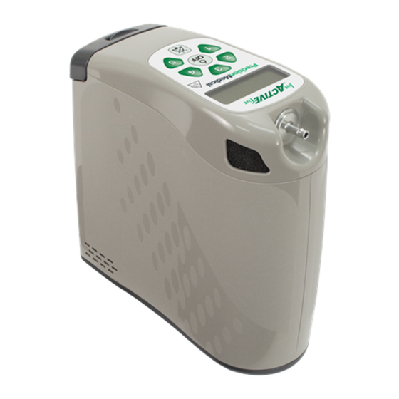
Page 4: Component Description
Component Description Oxygen Outlet Battery Fitting Handle Oxygen Air Inlet Outlet with Filter Fitting Display Screen Alert Indicator Pulse Selection Outlet Off Buttons (1-5) Button Pause Alert Button Battery Latch Battery Handle Battery Serial # Label External Power Connector Outlet... -
Page 5: General Disassembly
General Disassembly Tools and equipment required: • #1 Phillips screwdriver 1. Remove battery (508561) from unit 2. Place unit upside down on a level surface 3. Using screwdriver, take out 5 bottom screws (507128) and place to the side 4. Take bottom case (508535) off of unit and place to the side 5. -
Page 6: Sieve Bed Assembly Replacement (508697)
Sieve Bed Assembly Replacement (508697) Tools and equipment required: • #1 Phillips screwdriver Disassembly 1. Turn concentrator off, and remove the battery and external power from unit. 2. Turn unit upside down, and place on soft surface. Remove screws and bottom cover. 3. -
Page 7: Reassembly
Reassembly 1. Remove 4 plugs from new sieve bed assembly and slide it into the concentrator. 2. Gently push until sieve bed replacement is fully seated, flush with bottom surface. Replace bottom cover and secure screws. 3. Turn unit upright and insert battery. Gently push until battery is locked in place. Registration 1. -
Page 8: Air Outlet Filter Replacement (508583)
Air Outlet Filter Replacement (508583): Tools and equipment required: • Hex (Allen) wrench Disassembly 1. Remove cannula. 2. Using a clean hex (Allen) wrench, carefully remove the outlet by unscrewing it counter-clockwise. 3. The filter will be visible in the rear of the outlet once it is removed. 4. -
Page 9: Pc Board Replacement (508552)
PC Board Replacement (508552): *Ensure to follow Electrostatic Discharge procedures to avoid damage to electronic components Tools and equipment required: • #1 Phillips screwdriver • Needle nose pliers Disassembly 1. Follow steps 1 thru 7 of the “General Disassembly” section in this manual. 2. - Page 10 4. On back of battery separator plate (508539), remove the 2 top screws (508662) that attach the battery separator plate (508539) to the top case (508534). Top Case (508534) Screw x2 (508662) Battery Separator Plate (508539) 5. Carefully turn top case (508534) toward PC board (508552) and remove the 2 ribbon cables from the PC board. PC Board (508552) Top Case (508534) Ribbon Cables...
- Page 11 7. Using pliers, carefully remove the tubing that connects to the product tank pressure sensor and dose tank pressure sensor on the PC board (508552). Also remove both tubing pieces from the inspiratory sensor on the PC Board (508552). Dose Tank Inspiratory Pressure Sensor...
-
Page 12: Reassembly
Reassembly 1. With new PC board, connect the wires from the compressor assembly and power interface board to the bottom of the PC board. 2. Connect the wires from the fan and supply valve. 3. Attach the board to the unit by screwing in the screw (508351) that holds the PC board (508552) to the top separator plate (508538). -
Page 13: Compressor Replacement (508525)
Compressor Replacement (508525): Tools and equipment required: • #1 Phillips screwdriver • Needle nose pliers • Small diagonal wire cutters Disassembly 1. Follow steps 1 thru 7 of the “General Disassembly” section in this manual. 2. Remove the screw (503956) holding the PC board (508552) onto the battery separator plate (508539). Battery Separator Plate (508539) Screw (503956) - Page 14 4. Cut and remove the zip-tie (502776) from the compressor vacuum inlet. Disconnect the tubing from the compressor vacuum inlet. Compressor Vacuum Inlet Zip-tie (502776) 5. Cut and remove the zip-tie (502776) from the compressor pressure outlet elbow (505806). Disconnect the tubing from the compressor pressure outlet elbow (505806).
- Page 15 7. Remove the 2 screws (503264) holding the compressor assembly (508525) to the silicone isolation mount (508554). Screw (503264) Silicone Isolation Mount 8. Remove the compressor assembly (508525) from the silicone isolation mount (508554).
-
Page 16: Reassembly
Reassembly 1. Place the new compressor assembly (508525) onto the silicone isolation mount (508554). 2. Connect the hose from the compressor inlet filter assembly (508611) onto the compressor pressure inlet elbow (505806). 3. Connect the hose from the cooling coil (508677) onto the compressor pressure outlet elbow (505806). Place new zip- tie (502776) around the tubing on the compressor pressure outlet elbow. -
Page 17: Oxygen Sensor Replacement (508419)
Oxygen Sensor Replacement (508419): *Ensure to follow Electrostatic Discharge procedures to avoid damage to electronic components Tools and equipment required: • #1 Phillips screwdriver • Needle nose pliers Disassembly 1. On back of battery separator plate (508539), remove the 2 top screws (508662) that attach the battery separator plate (508539) to the top case (508534). - Page 18 3. Disconnect the wires from the PC board to the O2 sensor (508419). Sensor Sensor Barb Tubing Sensor Wires 4. Disconnect the tubing from both barbs on the O2 sensor (508419). Sensor Barbs Sensor Tubing 5. With one hand, pull back on the locking tab located on the top separator plate (508538). With the other hand, pull the O2 sensor (508419) up and remove.
-
Page 19: Reassembly
Reassembly 1. With the new O2 sensor (508419), align the O2 circuit board with the slots in the top separator plate (508538). Make sure the wire connector is upward. Sensor Circuit Board Slot 2. Slide the O2 sensor into the slots and press until the O2 sensor locks into place with the locking tab. Locking Tab 3. -
Page 20: Checking The Oxygen Purity
*Do not block the outlet while in the test mode. Damage to the device may occur and is not covered under warranty. 1. Attach the PM4155 “Live Active Five” Portable Oxygen Concentrator to the oxygen purity test device. 2. Remove all external power sources. -
Page 21: Warnings
This device is not to be used for support or to sustain life. This device is intended to provide supplemental oxygen only. This device is not intended for newborn and infant use. Precision Medical Inc, and your equipment provider are accountable for ensuring the compatibility of the device and all of the parts or accessories used. -
Page 22: Specifications
Class II Electrical Shock Protection, Type BF Applied Part, IP22 Ingress Protection Electrical Classification: Rating, Continuous Operation The Live Active Five Portable Oxygen Concentrator has been designed, tested, and certified to the following regulatory standards. Regulatory Listings: ANSI/AAMI 60601-1 Ed 3.1... -
Page 23: Recommended Preventative Maintenance
The device is specifically designed to minimize routine preventive maintenance. Except for tasks described below, only trained personnel should perform preventive maintenance or performance adjustments on the device and its equipment. Users should contact your provider or Precision Medical for service. WARNING Prior to cleaning, ensure the device is turned off, unplug any external power sources and remove battery. -
Page 24: Cleaning And Disinfection Between Users
Cleaning and Disinfection between Users To prevent infection and eliminate possible pathogen exchange between users due to contamination, cleaning and disinfection of the device and its accessories shall be performed by qualified personnel when used between users. 1. Remove battery and disconnect all external power from the device. 2. - Page 25 If operating outside the “Operating Environment Ranges,” an alert may occur and the POC may shut down. If the device fails to operate properly, refer to the following charts for possible causes and solutions. If necessary, contact your Provider or Precision Medical, Inc. Device Does Not Turn On or Does Not Stay On...
- Page 26 Press setting to restart. If there are 5 unsuccessful restart attempts in less than 5 minutes, service of the device will be required. Connect to an alternative oxygen source and contact your home care provider or Precision Medical. 508791 Rev0...