
Subscribe to Our Youtube Channel
Related Manuals for Premier Mounts CONVERGENT TVF Series


Summary of Contents for Premier Mounts CONVERGENT TVF Series
- Page 1 SERIES: TVF INSTALLATION GUIDE Convergent Series Video Wall Mount For Leyard TVF LED Cabinets www.premiermounts.com | North America 800.368.9700 | International +1-714-632-7100 9500275 v1.4 2620 Palisades Drive, Corona, CA 92882 USA publ. 01/24/19...
-
Page 2: Caution Statements
4. ALL LED CABINETS MUST BE POWER ON TESTED PRIOR TO ANY INSTALLATION. 5. PREMIER MOUNTS RECOMMENDS THE HANDLING LED CABINETS BY AN INDUSTRY QUALIFIED PROFESSIONAL. 6. PREMIER MOUNTS IS NOT RESPONSIBLE FOR DEFECTS, MISUSE, OR IMPROPER HANDLING OF THE LED CABINETS. Tools for Installation: 00.0... - Page 3 TVF - Installation Guide DETERMINE THE OVERALL VIDEO WALL DIMENSION LASER LEVEL Available Imperial Metric The overall dimensions of any video wall array can be Size (Inches) (Milimeters) calculated by using the table within this page. 2 Wide 47.60 1209.5 The desired array size is a combination of available sizes.
- Page 4 - TVF Installation Guide ITEM #. PART NO. DESCRIPTION 4000-106-111-LX Vertical Rail 1V 4000-106-112-LX Horizontal Rail 2H 4000-106-122-LX Vertical Rail 2V 4000-106-113-LX Horizontal Rail 3H 4000-106-123-LX Vertical Rail 3V 4000-106-114-LX Horizontal Rail 4H 4000-106-124-LX Vertical Rail 4V 4000-106-125-LX Vertical Rail 5V 4000-106-126-LX Vertical Rail 6V 4 WIDE...
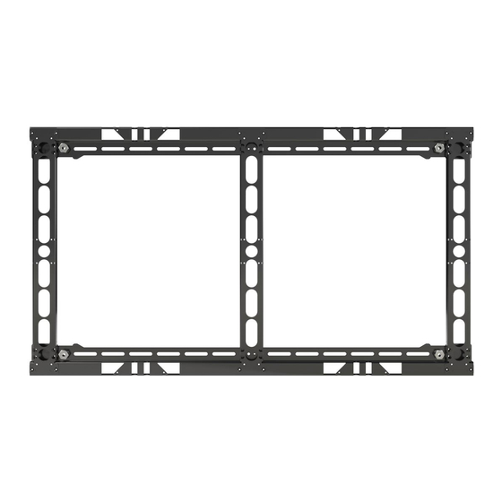
- Page 5 TVF - Installation Guide METHOD 1 1. Install the Vertical and Horizontal Rails together using (4) M5x 8mm Flat Head Screw per. 2. Install 5/8”-11 Bolt with Hole onto each threaded extrusion for ease of installation in sequential step. Horizontal Rail Vertical Rail...
- Page 6 - TVF Installation Guide 1. Place a level on top of the mount and reinstall or adjust the support screws if necessary. 2. Secure the first mounting location by sliding a Wall Anchor Plate behind the mount and fasten using 5/16” x 3 Hex Lag and 5/16” Washer. 3.
- Page 7 TVF - Installation Guide METHOD 2 LASER / LEVEL WALL WALL 00.0 Wall Anchor Plate Wall Anchor Plate 1. Install (2) 5/8”-11 Bolt with Hole onto the threaded extrusion. 2. Place the first Horizontal Rail on the wall. 3. Secure the first mounting location by sliding a Wall Anchor Plate behind the mount and fasten using 5/16”...
- Page 8 - TVF Installation Guide ASSEMBLE THE LOWER SECTION OF THE MOUNT 1. Securely fasten each Vertical Rail onto a mounted Horizontal Rail using (2) M5 x 8mm Flat Head Screw per end. 2. Fasten the Lower Horizontal Rail but do not anchor until the mount is perfectly square. See sequential step.
- Page 9 TVF - Installation Guide Multiple Unit Configuration Extend Horizontally the seems between two units To extend the width of the unit, follow the steps below. 1. Position the second Horizontal Rail side by side. 2. Place a support screw while maintaining a leveled horizontal rail to temporary hold in place.
- Page 10 - TVF Installation Guide Multiple Unit Configuration Extend Vertically To extend the height of the unit, follow the steps below. 1. Position multiple units adjust to each other. 2. Joint the units together using multiple Spacer Brackets and fasten using (8) M5 x 8mm Flat Head Screw per.
- Page 11 TVF - Installation Guide SQUARE AND LEVEL Inspect each bracket using a Square and Level tool. www.premiermounts.com | North America 800.368.9700 | International +1-714-632-7100 Page 11...
-
Page 12: Very Important
- TVF Installation Guide VERY IMPORTANT! VERIFYING THE DIAGONAL MEASUREMENTS FOR SQUARENESS Distance 1 The two diagonal measured distances must match Distance 2 1. Measure the distance from corner to corner with a tape measure. Place the tape measure tangent on the hole located at the corner of the mount. 2. - Page 13 TVF - Installation Guide FINAL ALIGMENT AND ADJUSTMENT 1. Tie a string from one end to the other end of the entire array. Tie horizontally and crisscross, especially for large video wall array. 2. Inspect for any gaps between the brackets and the string. 3.
- Page 14 - TVF Installation Guide Adjustments Uneven wall surfaces can be adjust by turning the Flush Bolt. 1/8” min. In / Out Clearance NOTES: If using the additional slots for mounting points, make sure that the floating frame is fully level to the wall vertically and horizontally. Must use shims (commercially available) on every slots being used to fill the void between the wall and the frame.
- Page 15 TVF - Installation Guide LEYARD TVF SERIES LED VIDEO INSTALLATION GUIDE must be read in conjunction with the recommended steps below. LED Cabinets to be handled by industry qualified professional. Improper installation may cause damage to the LEDs. 1. Detach the LED Module, exposing four mounting holes. 2.
- Page 16 1. Products must be packed securely to insure no further damage upon arrival at Premier Mounts\PDS. Improperly packaged items will be considered non-warranty. 2. Line rejects must be shipped to Premier Mounts\PDS in a separate box using a separate RMA number from any field rejects.
Need help?
Do you have a question about the CONVERGENT TVF Series and is the answer not in the manual?
Questions and answers