Table of Contents
Advertisement
Quick Links
UG506: xG23B 868-915 MHz 14 dBm Radio
Board User's Guide
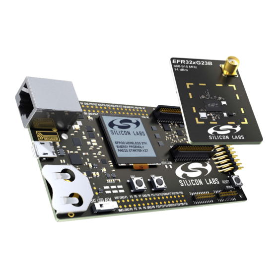
A Wireless Starter Kit with the BRD4204D Radio Board is an ex-
cellent starting point to get familiar with the EFR32™ Wireless
Gecko Wireless System-on-Chip, and it provides all necessary
tools for developing a Silicon Labs wireless application.
BRD4204D is a plug-in board for the Wireless Starter Kit Mainboard. It is a complete ref-
erence design for the EFR32ZG23 Wireless SoC, with matching networks for 14 dBm
output power, and an SMA connector for the 868-915 MHz band.
The Wireless Starter Kit Mainboard contains an on-board J-Link debugger with a Packet
Trace Interface and a Virtual COM port, enabling application development and debug-
ging the attached radio board as well as external hardware. The Mainboard also contains
sensors and peripherals for easy demonstration of some of the EFR32's many capabili-
ties.
This document describes how to use the BRD4204D Radio Board together with a Wire-
less Starter Kit Mainboard.
silabs.com | Building a more connected world.
BRD4204D RADIO BOARD FEATURES
• EFR32ZG23 Wireless Gecko Wireless
SoC with 512 kB Flash, and 64 kB RAM
(EFR32ZG23B010F512IM48)
• Dual band integrated radio transceiver
• 14 dBm output power
• Inverted-F PCB antenna (2.4 GHz)
• SMA antenna connector (868-915 MHz)
• 8 Mbit low-power serial flash for over-the-
air upgrades.
WIRELESS STK MAINBOARD FEATURES
• Advanced Energy Monitor
• Packet Trace Interface
• Virtual COM Port
• SEGGER J-Link on-board debugger
• External device debugging
• Ethernet and USB connectivity
• Silicon Labs Si7021 Relative Humidity and
Temperature sensor
• Low Power 128x128 pixel Memory LCD
• User LEDs / Pushbuttons
• 20-pin 2.54 mm EXP header
• Breakout pads for Wireless SoC I/O
• CR2032 coin cell battery support
SOFTWARE SUPPORT
• Simplicity Studio™
• Energy Profiler
• Network Analyzer
ORDERING INFORMATION
• SLWRB4204DA
Rev. 1.0
Advertisement
Table of Contents

Related Manuals for Silicon Laboratories BRD4204D


Summary of Contents for Silicon Laboratories BRD4204D
- Page 1 (EFR32ZG23B010F512IM48) • Dual band integrated radio transceiver BRD4204D is a plug-in board for the Wireless Starter Kit Mainboard. It is a complete ref- erence design for the EFR32ZG23 Wireless SoC, with matching networks for 14 dBm • 14 dBm output power output power, and an SMA connector for the 868-915 MHz band.
-
Page 2: Table Of Contents
Table of Contents 1. Introduction ....... . 4 1.1 Radio Boards ......4 1.2 Ordering Information . - Page 3 6.2.3 Limitations ......24 6.2.4 Troubleshooting ......25 7.
-
Page 4: Introduction
This document explains how to use the Wireless Starter Kit when the xG23 868-915 MHz 14 dBm Radio Board Radio Board (BRD4204D) is combined with a Wireless STK Mainboard. The combination of these two boards is hereby referred to as a Wireless Starter Kit (Wireless STK). -
Page 5: Hardware Overview
UG506: xG23B 868-915 MHz 14 dBm Radio Board User's Guide Hardware Overview 2. Hardware Overview 2.1 Hardware Layout The layout of the xG23 868-915 MHz 14 dBm Radio Board Wireless Starter Kit is shown in the figure below. Radio Board Breakout Pads Plug-in Radio Board On-board USB and Si7021 Humidity and... -
Page 6: Block Diagram
UG506: xG23B 868-915 MHz 14 dBm Radio Board User's Guide Hardware Overview 2.2 Block Diagram An overview of the xG23 868-915 MHz 14 dBm Radio Board Wireless Starter Kit is shown in the figure below. Board USB Mini-B Controller RJ-45 Ethernet Connector Connector UART... -
Page 7: Connectors
UG506: xG23B 868-915 MHz 14 dBm Radio Board User's Guide Connectors 3. Connectors This chapter gives you an overview of the Wireless STK Mainboard connectivity. The placement of the connectors is shown in the fig- ure below. VMCU VMCU Figure 3.1. Mainboard Connector Layout 3.1 J-Link USB Connector The J-Link USB connector is situated on the left side of the Wireless Starter Kit Mainboard. -
Page 8: Breakout Pads
UG506: xG23B 868-915 MHz 14 dBm Radio Board User's Guide Connectors 3.3 Breakout Pads Most pins of the EFR32 are routed from the radio board to breakout pads at the top and bottom edges of the Wireless STK Mainboard. A 2.54 mm pitch pin header can be soldered on for easy access to the pins. The figure below shows you how the pins of the EFR32 map to the pin numbers printed on the breakout pads. -
Page 9: Exp Header
UG506: xG23B 868-915 MHz 14 dBm Radio Board User's Guide Connectors 3.4 EXP Header The EXP header is an angled 20-pin expansion header that allows connection of peripherals or plugin boards to the kit. It is located on the right-hand side of the mainboard, and it contains several I/O pins that can be used with most of the EFR32 Wireless Gecko's fea- tures. -
Page 10: Expansion Header Pin-Out
UG506: xG23B 868-915 MHz 14 dBm Radio Board User's Guide Connectors 3.4.1 Expansion Header Pin-out The pin-routing on the EFR32 is very flexible, so most peripherals can be routed to any pin. However, many pins are shared between the Expansion Header and other functions on the Wireless STK Mainboard. Table 3.1 Expansion Header Pinout on page 10 includes an overview of the mainboard features that share pins with the Expansion Header. -
Page 11: Debug Connector
UG506: xG23B 868-915 MHz 14 dBm Radio Board User's Guide Connectors 3.5 Debug Connector The debug connector serves multiple purposes based on the "debug mode" setting which can be configured in Simplicity Studio. When the debug mode is set to "Debug IN", the debug connector can be used to connect an external debugger to the EFR32 on the radio board. -
Page 12: Simplicity Connector
UG506: xG23B 868-915 MHz 14 dBm Radio Board User's Guide Connectors 3.6 Simplicity Connector The Simplicity Connector enables the advanced debugging features, such as the AEM, the virtual COM port, and the Packet Trace Interface, to be used towards an external target. The pinout is illustrated in the figure below. VMCU VCOM_TX VCOM_RX... -
Page 13: Debug Adapter
UG506: xG23B 868-915 MHz 14 dBm Radio Board User's Guide Connectors 3.7 Debug Adapter The BRD8010A STK/WSTK Debug Adapter is an adapter board which plugs directly into the debug connector and the Simplicity Con- nector on the mainboard. It combines selected functionality from the two connectors to a smaller footprint 10-pin connector, which is more suitable for space-constrained designs. -
Page 14: Power Supply And Reset
With the switch in the USB position, radio boards with USB-support can be powered by a regulator on the radio board itself. BRD4204D does not contain a USB regulator, and setting the switch in the USB position will cause the EFR32 to be unpowered. -
Page 15: Efr32 Reset
UG506: xG23B 868-915 MHz 14 dBm Radio Board User's Guide Power Supply and Reset 4.3 EFR32 Reset The EFR32 Wireless SoC can be reset by a few different sources: • A user pressing the RESET button • The on-board debugger pulling the #RESET pin low •... -
Page 16: Peripherals
UG506: xG23B 868-915 MHz 14 dBm Radio Board User's Guide Peripherals 5. Peripherals The starter kit has a set of peripherals that showcase some of the features of the EFR32. Note that most EFR32 I/O routed to peripherals are also routed to the breakout pads or the EXP header, which must be taken into consideration when using these. -
Page 17: Memory Lcd-Tft Display
UG506: xG23B 868-915 MHz 14 dBm Radio Board User's Guide Peripherals 5.2 Memory LCD-TFT Display A 1.28-inch SHARP Memory LCD-TFT is available on the kit to enable interactive applications to be developed. The display has a high resolution of 128 x 128 pixels and consumes very little power. It is a reflective monochrome display, so each pixel can only be light or dark, and no backlight is needed in normal daylight conditions. -
Page 18: Serial Flash
UG506: xG23B 868-915 MHz 14 dBm Radio Board User's Guide Peripherals 5.3 Serial Flash The BRD4204D Radio Board is equipped with an 8 Mbit Macronix MX25R SPI flash that is connected directly to the EFR32. The figure below shows how the serial flash is connected to the EFR32. VMCU... -
Page 19: Si7021 Relative Humidity And Temperature Sensor
UG506: xG23B 868-915 MHz 14 dBm Radio Board User's Guide Peripherals 5.4 Si7021 Relative Humidity and Temperature Sensor The Si7021 I C relative humidity and temperature sensor is a monolithic CMOS IC integrating humidity and temperature sensor ele- ments, an analog-to-digital converter, signal processing, calibration data, and an I C Interface. -
Page 20: Virtual Com Port
UG506: xG23B 868-915 MHz 14 dBm Radio Board User's Guide Peripherals 5.5 Virtual COM Port An asynchronous serial connection to the board controller is provided for application data transfer between a host PC and the target EFR32. This eliminates the need for an external serial port adapter. Isolation &... -
Page 21: Host Interfaces
UG506: xG23B 868-915 MHz 14 dBm Radio Board User's Guide Peripherals 5.5.1 Host Interfaces Data can be exchanged between the board controller and the target device through the VCOM interface, which is then available to the user in two different ways: •... -
Page 22: Hardware Handshake
UG506: xG23B 868-915 MHz 14 dBm Radio Board User's Guide Peripherals 5.5.3 Hardware Handshake The VCOM peripheral supports basic RTS/CTS flow control. VCOM_CTS (target clear to send) is a signal that is output from the board controller and input to the target device. The board controller de-asserts this pin whenever its input buffer is full and it is unable to accept more data from the target device. -
Page 23: Board Controller
UG506: xG23B 868-915 MHz 14 dBm Radio Board User's Guide Board Controller 6. Board Controller The Wireless STK Mainboard contains a dedicated microcontroller for some of the advanced kit features provided. This microcontroller is referred to as the board controller and is not programmable by the user. The board controller acts as an interface between the host PC and the target device on the radio board, as well as handling some housekeeping functions on the board. -
Page 24: Command Examples
UG506: xG23B 868-915 MHz 14 dBm Radio Board User's Guide Board Controller 6.1.3 Command Examples PTI Configuration pti config 0 efruart 1600000 Configures PTI to use the "EFRUART" mode at 1.6 Mb/s. Serial Port Configuration serial config vcom handshake enable Enables hardware handshake on the VCOM UART connection. -
Page 25: Troubleshooting
UG506: xG23B 868-915 MHz 14 dBm Radio Board User's Guide Board Controller 6.2.4 Troubleshooting Problem Solution No data received after ending a After certain debugger operations the host computer manually disables SWO on the target in order debug session. to conserve power. This might cause SWO data to not appear if the target application initialized SWO before the debugger has disconnected. -
Page 26: Advanced Energy Monitor
UG506: xG23B 868-915 MHz 14 dBm Radio Board User's Guide Advanced Energy Monitor 7. Advanced Energy Monitor 7.1 Introduction Any embedded developer seeking to make their embedded code spend as little energy as the underlying architecture supports needs tools to easily and quickly discover inefficiencies in the running application. This is what the Simplicity Energy Profiler is designed to do. In real-time, the Energy Profiler will graph and log current as a function of time while correlating this to the actual target application code running on the EFR32. -
Page 27: Aem Accuracy And Performance
UG506: xG23B 868-915 MHz 14 dBm Radio Board User's Guide Advanced Energy Monitor 7.3 AEM Accuracy and Performance The AEM is capable of measuring currents in the range of 0.1 µA to 95 mA. For currents above 250 µA, the AEM is accurate within 0.1 mA. -
Page 28: On-Board Debugger
UG506: xG23B 868-915 MHz 14 dBm Radio Board User's Guide On-Board Debugger 8. On-Board Debugger The Wireless STK Mainboard contains an integrated debugger, which can be used to download code and debug the EFR32. In addition to programming a target on a plug-in radio board, the debugger can also be used to program and debug external Silicon Labs EFM32, EFM8, EZR32, and EFR32 devices connected through the debug connector. -
Page 29: Debug Modes
UG506: xG23B 868-915 MHz 14 dBm Radio Board User's Guide On-Board Debugger 8.2 Debug Modes To program external devices, use the debug connector to connect to a target board and set the debug mode to [Out]. The same con- nector can also be used to connect an external debugger to the EFR32 Wireless SoC on the kit by setting debug mode to [In]. Selecting the active debug mode is done in Simplicity Studio. -
Page 30: Debugging During Battery Operation
UG506: xG23B 868-915 MHz 14 dBm Radio Board User's Guide On-Board Debugger 8.3 Debugging During Battery Operation When the EFR32 is battery-powered and the J-Link USB is still connected, the on-board debug functionality is available. If the USB power is disconnected, the Debug IN mode will stop working. If debug access is required when the target is running off another energy source, such as a battery, and the board controller is powered down, make direct connections to the GPIO used for debugging. -
Page 31: Kit Configuration And Upgrades
UG506: xG23B 868-915 MHz 14 dBm Radio Board User's Guide Kit Configuration and Upgrades 9. Kit Configuration and Upgrades The kit configuration dialog in Simplicity Studio allows you to change the J-Link adapter debug mode, upgrade its firmware, and change other configuration settings. -
Page 32: Schematics, Assembly Drawings, And Bom
UG506: xG23B 868-915 MHz 14 dBm Radio Board User's Guide Schematics, Assembly Drawings, and BOM 10. Schematics, Assembly Drawings, and BOM Schematics, assembly drawings, and bill of materials (BOM) are available through Simplicity Studio when the kit documentation pack- age has been installed. They are also available from the kit page on the Silicon Labs website: http://www.silabs.com/. silabs.com | Building a more connected world. -
Page 33: Kit Revision History
UG506: xG23B 868-915 MHz 14 dBm Radio Board User's Guide Kit Revision History 11. Kit Revision History The kit revision can be found printed on the kit packaging label, as outlined in the figure below. xG23B 868-915 MHz 14 dBm Radio Board SLWRB4204D 04-04-21 124802042... -
Page 34: Document Revision History
UG506: xG23B 868-915 MHz 14 dBm Radio Board User's Guide Document Revision History 12. Document Revision History Revision 1.0 Sep 2021 • Initial document release. silabs.com | Building a more connected world. Rev. 1.0 | 34... - Page 35 Note: This content may contain offensive terminology that is now obsolete. Silicon Labs is replacing these terms with inclusive language wherever possible. For more information, visit www.silabs.com/about-us/inclusive-lexicon-project Trademark Information Silicon Laboratories Inc. , Silicon Laboratories , Silicon Labs , SiLabs...
Need help?
Do you have a question about the BRD4204D and is the answer not in the manual?
Questions and answers