Table of Contents
Advertisement
Quick Links
UG532: ZGM230S Dev Kit User's Guide
The ZGM230S Dev Kit is a low-cost, small form factor develop-
ment and evaluation platform for the ZGM230S Z-Wave SiP Mod-
ule (System-in-Package Module).
The board is a small and cost-effective, feature-rich, prototype and development platform
based on the ZGM230S Z-Wave System-in-Package Module. The ZGM230S Dev Kit is
an ideal platform for developing energy-friendly connected IoT devices.
A built-in SEGGER J-Link debugger ensures easy debugging through the USB Type-C
connector.
silabs.com | Building a more connected world.
Copyright © 2022 by Silicon Laboratories
TARGET DEVICE
• ZGM230S Z-Wave SiP Module
(ZGM230SB27HGN3)
• +14 dBm TX power
• -110.9 dBm RX sensitivity @100 kbps
• 32-bit ARM® Cortex®-M33 with 39 MHz
maximum operating frequency
• 512 kB flash and 64 kB RAM
• Integrated DC-DC converter
KIT FEATURES
• SMA connector for antenna connection
• Power control of on-board peripherals for
ultra-low power operation
• Relative humidity and temperature sensor
• Ambient light sensor
• Hall effect sensor
• 6-axis inertial sensor
• LC sensor for metal detection
• Pressure sensor
• 8 Mbit flash for OTA programming and
data logging
• RGB LED, two single color LEDs, and two
push buttons
• 20-pin 2.54 mm breakout pads
• Qwiic® connector
• SEGGER J-Link on-board debugger
• Virtual COM port
• Packet Trace Interface (PTI)
• Mini Simplicity connector for AEM and
packet trace using external Silicon Labs
debugger
• USB or coin cell battery powered
• External battery connector
SOFTWARE SUPPORT
• Simplicity Studio™
Rev. 1.0
Advertisement
Table of Contents

Related Manuals for Silicon Laboratories UG532


Summary of Contents for Silicon Laboratories UG532
- Page 1 UG532: ZGM230S Dev Kit User's Guide The ZGM230S Dev Kit is a low-cost, small form factor develop- TARGET DEVICE ment and evaluation platform for the ZGM230S Z-Wave SiP Mod- ule (System-in-Package Module). • ZGM230S Z-Wave SiP Module (ZGM230SB27HGN3) The board is a small and cost-effective, feature-rich, prototype and development platform •...
-
Page 2: Table Of Contents
Table of Contents 1. Introduction ....... . 4 1.1 Kit Contents ....... 4 1.2 Getting Started . - Page 3 5.4 EMC Compliance Recommendations ..... .29 5.4.1 Recommendations for 868 MHz ETSI ETSI EN 300-200-1 Compliance ..29 5.4.2 Recommendations for 915 MHz FCC 15.247 Compliance .
-
Page 4: Introduction
UG532: ZGM230S Dev Kit User's Guide Introduction 1. Introduction The ZGM230S Dev Kit (OPN: ZGM230-DK2603A) has been designed to inspire customers to make battery-operated IoT devices with the Silicon Labs ZGM230S Z-wave System-in-Package (SiP) Module. The highlights of the board include six different environmental sensors accessible to the ZGM230S wireless MCU. -
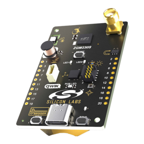
Page 5: Kit Hardware Layout
UG532: ZGM230S Dev Kit User's Guide Introduction 1.4 Kit Hardware Layout ZGM230S Dev Kit layout is shown below. SMA Antenna Connector 35.6 mm Top View Bottom View ZGM230S Z-Wave 800 Reset Button SiP Module LEDs Humidity and Temperature Sensor Hall Effect... -
Page 6: Specifications
UG532: ZGM230S Dev Kit User's Guide Specifications 2. Specifications 2.1 Recommended Operating Conditions The following table is intended to serve as a guideline for correct use of the ZGM230S Dev Kit, indicating typical operating conditions and some design limits. Table 2.1. Recommended Operating Conditions... -
Page 7: Current Consumption
UG532: ZGM230S Dev Kit User's Guide Specifications 2.2 Current Consumption The table below summarizes the data sheet current consumption of the various components on the board. The operating current of the board greatly depends on the application. The number of enabled sensors, how often they are sampled, and how often the radio is transmitting or receiving are examples of factors that influence the operating current. - Page 8 UG532: ZGM230S Dev Kit User's Guide Specifications Parameter Symbol Condition Unit Minimum Board Current Minimum total board current consumption for VMCU = 3.3 V µA BOARD Consumption with ZGM230S in EM4S, the USB cable disconnected, and all peripherals either in sleep mode or disconnected Note: 1.
-
Page 9: Hardware
UG532: ZGM230S Dev Kit User's Guide Hardware 3. Hardware The core of the ZGM230S Dev Kit is the ZGM230S Z-Wave SiP Module (System-in-Package Module). The board also contains several peripherals connected to the ZGM230S. Refer to section 1.4 Kit Hardware Layout for placement and layout of the hardware compo- nents. -
Page 10: Power Supply
UG532: ZGM230S Dev Kit User's Guide Hardware 3.2 Power Supply The kit can be powered through one of these interfaces: • USB Type-C • Battery (CR2032 battery or external battery connected through 2-pin battery header) • Mini Simplicity connector The figure below shows the power options available on the kit and illustrates the main system power architecture. -
Page 11: Peripherals
UG532: ZGM230S Dev Kit User's Guide Hardware 3.4 Peripherals The ZGM230S Dev Kit contains a set of peripherals that can be accessed from the ZGM230S. All the peripherals have enable signals which can be used to completely turn off the peripherals that are not in use, or they can be put into a state that draws a minuscule amount of power. -
Page 12: Si7021 Relative Humidity And Temperature Sensor
UG532: ZGM230S Dev Kit User's Guide Hardware 3.4.1 Si7021 Relative Humidity and Temperature Sensor The Si7021 I C relative humidity and temperature sensor is a monolithic CMOS IC integrating humidity and temperature sensor ele- ments, an analog-to-digital converter, signal processing, calibration data, and an I C interface. -
Page 13: Icm-20689 6-Axis Inertial Sensor
UG532: ZGM230S Dev Kit User's Guide Hardware 3.4.3 ICM-20689 6-Axis Inertial Sensor The ICM-20689 is a 6-axis inertial sensor consisting of a 3-axis gyroscope and a 3-axis accelerometer. The sensor detects acceleration and angular rate in and around the X-, Y-, and Z-axes with integrated 16-bit ADCs and programmable digital filters. -
Page 14: Veml6035 Ambient Light Sensor
UG532: ZGM230S Dev Kit User's Guide Hardware 3.4.4 VEML6035 Ambient Light Sensor The VEML6035 is an ambient light sensor with I C digital interface. On the ZGM230S Dev Kit, the VEML6035 is connected through a switch. The switch must therefore be enabled by setting PC07 high before it can be used by the application. -
Page 15: External Memory
UG532: ZGM230S Dev Kit User's Guide Hardware 3.4.6 External Memory The ZGM230S Dev Kit includes an 8 Mbit Macronix SPI Flash that is connected directly to the ZGM230S. The MX25R series are ultra- low power serial flash devices, so there is no need for a separate enable switch to keep current consumption down. However, it is im- portant that the flash is always put in deep power down mode when not used. -
Page 16: Metal Detector (Lc Sensor)
UG532: ZGM230S Dev Kit User's Guide Hardware 3.4.8 Metal Detector (LC Sensor) An inductive-capacitive sensor for demonstrating the Low Energy Sensor Interface (LESENSE) is located on the top left of the board. The LESENSE peripheral uses the voltage digital-to-analog converter (VDAC) to set up an oscillating current through the inductor and then uses the analog comparator (ACMP) to measure the oscillation decay time. -
Page 17: On-Board Debugger
UG532: ZGM230S Dev Kit User's Guide Hardware 3.5 On-board Debugger The ZGM230S Dev Kit contains a microcontroller separate from the ZGM230S Z-Wave SiP Module that provides the user with an on- board J-Link debugger through the USB Type-C port. This microcontroller is referred to as the "on-board debugger" and is not program- mable by the user. -
Page 18: Connectors
UG532: ZGM230S Dev Kit User's Guide Hardware 3.6 Connectors The ZGM230S Dev Kit features a Mini Simplicity Connector, a USB Type-C connector, and 20 breakout pads that follow the EXP head- er pinout. The connectors are placed on the top side of the board, and their placement and pinout are seen shown the figure below. For additional information on the connectors see the following sub-chapters. -
Page 19: Breakout Pads
UG532: ZGM230S Dev Kit User's Guide Hardware 3.6.1 Breakout Pads Twenty breakout pads, which follow the EXP header pinout, are provided and allow connection of peripherals or add-on boards. Ten of the pads are located along the left side of the board and ten are located on the right side. The breakout pads expose I/O pins that can be used with most of the ZGM230S's features. -
Page 20: Qwiic Connector
UG532: ZGM230S Dev Kit User's Guide Hardware 3.6.2 Qwiic Connector The ZGM230S Dev Kit features a Qwiic connector compatible with Qwiic Connect System hardware. The Qwiic connector provides an easy way to expand the functionality of the ZGM230S Dev Kit with sensors, LCDs, and other peripherals over the I C interface. -
Page 21: Debugging
UG532: ZGM230S Dev Kit User's Guide Debugging 4. Debugging The ZGM230S Dev Kit contains an on-board SEGGER J-Link Debugger that interfaces to the target ZGM230S using the Serial Wire Debug (SWD) interface. The debugger allows the user to download code and debug applications running in the target ZGM230S. Addi- tionally, it also provides a VCOM port to the host computer that is connected to the target device's serial port for general purpose com- munication between the running application and the host computer. -
Page 22: On-Board Debugger
UG532: ZGM230S Dev Kit User's Guide Debugging 4.1 On-board Debugger The on-board debugger is a SEGGER J-Link debugger running on an EFM32 Giant Gecko. The debugger is directly connected to the debug and VCOM pins of the target ZGM230S. When the debug USB cable is inserted, the on-board debugger is automatically activated, and takes control of the debug and VCOM interfaces. -
Page 23: Radio
UG532: ZGM230S Dev Kit User's Guide Radio 5. Radio 5.1 Introduction The ZGM230SB27HGN3 module includes a 50 Ω-matched RFIO pin. On the ZGM230S Dev Kit (BRD2603A board), the pin is connec- ted to an SMA connector, enabling conducted measurements or attachment of an external antenna for radiated measurements. -
Page 24: Rf Performance
UG532: ZGM230S Dev Kit User's Guide Radio 5.2.2.2 FCC15.247 Emission Limits for the 902-928 MHz Band FCC 15.247 allows conducted output power up to 1 Watt (30 dBm) in the 902-928 MHz band. For spurious emmissions the limit is -20 dBc based on either conducted or radiated measurement, if the emission is not in a restricted band. The restricted bands are speci- fied in FCC 15.205. - Page 25 UG532: ZGM230S Dev Kit User's Guide Radio Figure 5.1. Typical Output Spectrum of the BRD2603A in the 868 MHz Band Figure 5.2. Typical Output Spectrum of the BRD2603A in the 908 MHz Band silabs.com | Building a more connected world.
-
Page 26: Radiated Power Measurements
UG532: ZGM230S Dev Kit User's Guide Radio Figure 5.3. Typical Output Spectrum of the BRD2603A in the 921 MHz Band As shown in the figures, the fundamental is a bit lower than 14 dBm in the 868 MHz bans, and a bit higher than 14 dBm in the bands above 900 MHz. - Page 27 UG532: ZGM230S Dev Kit User's Guide Radio 5.3.2.1 Radiated Measurements For the radiated power measurements, an external compressed whip antenna (LPRS ANT-SS900) was used as a transmitter antenna. It was connected to the on-board SMA connector. The measured radiated powers are shown in the table below.
- Page 28 UG532: ZGM230S Dev Kit User's Guide Radio Table 5.5. Maximums of the Measured Radiated Powers of BRD2603A Measured Unmodulated Frequency (921 MHz) Orientation Margin [dB] Limit in EIRP [dBm] EIRP [dBm] Fund 14.3 XZ/H 24.0 -57.7 XY/V 27.7 -30.0 -61.0 XZ/H 31.0...
-
Page 29: Emc Compliance Recommendations
UG532: ZGM230S Dev Kit User's Guide Radio 5.3.2.2 Antenna Pattern Measurements The measured normalized antenna patterns are shown in the following figures. Normalized Radiation Pattern [dB], BRD2603A, Normalized Radiation Pattern [dB], BRD2603A, Normalized Radiation Pattern [dB], BRD2603A, 868.4 MHz, XY cut 868.4 MHz, XZ cut... -
Page 30: Recommendations For 915 Mhz Fcc 15.247 Compliance
UG532: ZGM230S Dev Kit User's Guide Radio 5.4.2 Recommendations for 915 MHz FCC 15.247 Compliance As shown in the previous section, the BRD2603A board is compliant with the emission limits of the FCC 15.247 regulation in the 908.4 MHz band with 14 dBm output power. -
Page 31: Schematics, Assembly Drawings, And Bom
UG532: ZGM230S Dev Kit User's Guide Schematics, Assembly Drawings, and BOM 6. Schematics, Assembly Drawings, and BOM Schematics, assembly drawings, and bill of materials (BOM) are available through Simplicity Studio when the kit documentation pack- age has been installed. They are also available from the kit page on the Silicon Labs website: silabs.com. -
Page 32: Kit Revision History And Errata
UG532: ZGM230S Dev Kit User's Guide Kit Revision History and Errata 7. Kit Revision History and Errata 7.1 Revision History The kit revision can be found printed on the box label of the kit, as outlined in the figure below. The kit revision history is summarized in the table below. -
Page 33: Board Revision History And Errata
UG532: ZGM230S Dev Kit User's Guide Board Revision History and Errata 8. Board Revision History and Errata 8.1 Revision History The board revision can be found laser printed on the board, and the board revision history is summarized in Table 8.1 Board Revision History on page 33. -
Page 34: Document Revision History
UG532: ZGM230S Dev Kit User's Guide Document Revision History 9. Document Revision History Revision 1.0 June 2022 • Initial document release. silabs.com | Building a more connected world. Rev. 1.0 | 34... - Page 35 Note: This content may contain offensive terminology that is now obsolete. Silicon Labs is replacing these terms with inclusive language wherever possible. For more information, visit www.silabs.com/about-us/inclusive-lexicon-project Trademark Information Silicon Laboratories Inc. , Silicon Laboratories , Silicon Labs , SiLabs...
Need help?
Do you have a question about the UG532 and is the answer not in the manual?
Questions and answers