Advertisement
Quick Links
NCP1351PRINTGEVB
NCP1351 16 V/32 V – 40 W
Printer Power Supply
Evaluation Board
User's Manual
Description
The present document describes a printer power supply
operated by the NCP1351, a fixed
controller. The board can deliver 10 W average on a 16 V
output and 30 W average on a 32 V output with a transient
peak power capability of 80 W. It however exhibits a low
standby power: below 150 mW at no load whatever the input
voltage. Let us first review the benefit of using the
NCP1351:
The NCP1351 at a Glance
Fixed t
, Variable t
Current-mode Control:
on
off
Implementing a fixed peak current mode control (hence
the more appropriate term "quasi-fixed" t
modulates the off time duration according to the output
power demand. In high power conditions, the switching
frequency increases until a maximum is hit. This upper limit
depends on an external capacitor selected by the designer. In
light load conditions, the off time expands and the NCP1351
operates at a lower frequency. As the frequency reduces, the
contribution of all frequency-dependent losses accordingly
goes down (driver current, drain capacitive losses, switching
losses), naturally improving the efficiency at various load
levels.
Peak Current Compression at Light Loads:
Reducing the frequency will certainly force the converter
to operate into the audible region. To prevent the transformer
mechanical resonance, the NCP1351 gradually reduces –
compresses – the peak current setpoint as the load becomes
lighter. When the current reaches 30% of the nominal value,
the compression stops and the off duration keeps expanding
towards low frequencies.
Low Standby-power:
The frequency reduction technique offers an excellent
solution for designers looking for low standby power
converters. Also, compared to the skip-cycle method, the
smooth off time expansion does not bring additional ripple
in no-load conditions: the output voltage remains quiet.
© Semiconductor Components Industries, LLC, 2012
October, 2012 − Rev. 0
t
/variable off time
on
), the NCP1351
on
1
http://onsemi.com
EVAL BOARD USER'S MANUAL
Natural Frequency Dithering:
The quasi-fixed t
mode of operation improves the EMI
on
signature since the switching frequency varies with the
natural bulk ripple voltage.
Extremely Low Start-up Current:
Built on a proprietary circuitry, the NCP1351 startup
section does not consume more than 10 mA during the
startup sequence. The designer can thus easily combine
startup time and standby consumption.
Overload Protection Based on Fault Timer:
Every designer knows the pain of building converters
where a precise over current limit must be obtained. When
the fault detection relies on the auxiliary V
increases. Here, the NCP1351 observes the lack of feedback
current and starts a timer to countdown. At the end of its
charge, the timer either triggers an auto-recovery sequence
(auto-restart, B and D versions) or permanently latches-off
(A and C). On C and D versions the fault timer is started at
an output power corresponding to 60% of the maximum
deliverable power; to allow transient peak power delivery.
Latch Fault Input:
A dedicated input lets the designer externally trigger the
latch to build additional protections such as over-voltage
(OVP) or over-temperature (OTP).
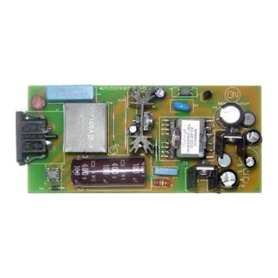
Figure 1. NCP1351 Evaluation Board
, the pain even
CC
Publication Order Number:
EVBUM2150/D
Advertisement

Related Manuals for ON Semiconductor NCP1351 Series


Summary of Contents for ON Semiconductor NCP1351 Series
- Page 1 NCP1351PRINTGEVB NCP1351 16 V/32 V – 40 W Printer Power Supply Evaluation Board User's Manual http://onsemi.com EVAL BOARD USER’S MANUAL Description Natural Frequency Dithering: The present document describes a printer power supply The quasi-fixed t mode of operation improves the EMI operated by the NCP1351, a fixed /variable off time signature since the switching frequency varies with the...
- Page 2 Input Voltage Range (LPS) ® The transformer has been derived using the Excel • Latched Short-circuit Protection spreadsheet available from the ON Semiconductor website • Latched Over-voltage Protection which also gives transformer parameters. We came up to the • Latch Recovery Time below 3 s following values: •...
- Page 3 NCP1351PRINTGEVB Two 330 kW resistors in series with a 60 V zener diode controller is latched (a direct connection to the AC line ensure a clean start-up sequence with the 4.7 mF capacitor would also work). Despite a small value for C , the V still ), not from the bulk capacitor as it is usually done;...
- Page 4 NCP1351PRINTGEVB Rcomp −N.Vin 470 k 2.2 k OPP Adjust 220 p 1N4148 Vaux NCP1351 Rsense Figure 4. A Simple Arrangement Provides an Adjustable Overpower Power Compensation A simple resistor connected between the auxiliary Overpower Protection Level: The power supply is able to deliver a peak power of 85 W winding (that swings negative during the ON time) and the during 500 ms from 85 Vac to 270 Vac.
- Page 5 NCP1351PRINTGEVB Scope Shots Below are some oscilloscope shots gathered on the evaluation board: 2.7 s 32 V Figure 6. Start-up Time, V = 85 Vac DRAIN Figure 7. Maximum Output Power, V = 265 Vac Conclusion The printer power supply built with the NCP1351 exhibits The limited number of surrounding components around an excellent performance on several parameters like the the controller associated to useful features (timer-based...
-
Page 6: Pcb Layout
NCP1351PRINTGEVB PCB LAYOUT Figure 8. Top Side Components Figure 9. Copper Traces Figure 10. SMD Components http://onsemi.com... - Page 7 NCP1351PRINTGEVB Fuse DF05M 220 n 1N4007 ELF−25F108A 0.33 sense 100 m 3.4 k 3.3 M Jitter 3.3 M 180 p 4.7 M OptoBase 1.5 m 2.7 k C101 NCP1351A 100 n Timer 100 n 10 n 17 V R11 1 k 60 V 330 k 330 k...
- Page 8 Y1 Capacitor 2.2 nF/250 Vac Radial CD12−E2GA222MYNS SMD Resistor SOD−1206 Vishay CRCW12060000Z0EA 0 W/0.25 W High-voltage 200 mA/200 V − SOT−23 ON Semiconductor BAS20LT1G Switching Diode Fast-recovery 1 A/600 V − Axial ON Semiconductor 1N4937G Rectifier D5, D7 Schottky 20 A/100 V −...
-
Page 9: Test Procedure
NCP1351PRINTGEVB Table 4. BILL OF MATERIAL FOR THE NCP1351 40 W PRINTER EVALUATION BOARD (continued) Manufacturer Substitution Lead Designator Qty. Description Value Tolerance Footprint Manufacturer Part Number Allowed Free Resistor 4.7 MW/0.33 W Axial − − R5, R6 SMD Resistor 330kW/0.25 W SOD−1206 Vishay... - Page 10 NCP1351PRINTGEVB 3. Connect an electronic load between pins +32 V The power supply should go to short-circuit and GND, and set up a current of 1 A. Connect protection. Measure the output voltages that another electronic load between pins +16 V and should be 0 V.
-
Page 11: Technical Support
LIMITATIONS OF LIABILITY: ON Semiconductor shall not be liable for any special, consequential, incidental, indirect or punitive damages, including, but not limited to the costs of requalification, delay, loss of profits or goodwill, arising out of or in connection with the board, even if ON Semiconductor is advised of the possibility of such damages. In no event shall ON Semiconductor’s aggregate liability from any obligation arising out of or in connection with the board, under any theory of liability, exceed the purchase price paid for the board, if any.
Need help?
Do you have a question about the NCP1351 Series and is the answer not in the manual?
Questions and answers