
Related Manuals for ON Semiconductor NCP102


Summary of Contents for ON Semiconductor NCP102
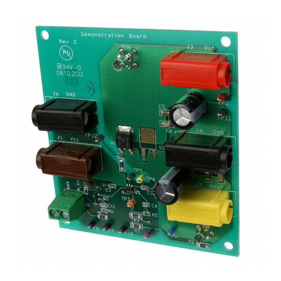
- Page 1 NCP102 Demonstration Board Test Procedure Figure 1 Test Setup 1/22/08 1 of 4 REV 1...
- Page 2 4 ADC; for example, Kikusui PLZ303W. Test Procedure: Establish Setup Connect the NCP102 Demonstration Board as shown in Figure 1. Adjust the N_Enable supply to 4.5VDC while observing the indicator on the supply. Note: for measurement accuracy, the DMMs must be connected to the Demonstration Board terminals and not the DC supply or load terminals.
- Page 3 NCP102 Demonstration Board Test Procedure Adjust the Vcc supply to 5.0VDC while observing DMM 1 (not the indicator on the DC supply). Adjust the Vin supply to 1.800VDC while observing DMM 2 (not the indicator on the DC supply). Disable the electronic load so that it is neither sinking nor sourcing current.
- Page 4 NCP102 Demonstration Board Test Procedure If Vcc= 5.0VDC (DMM 1), go to Step 12. Adjust the Vcc supply to 5.0VDC, as indicated on DMM 1. Repeat steps 1 through 9 of this section. Verify that Vout (DMM 3) equals zero VDC.
Need help?
Do you have a question about the NCP102 and is the answer not in the manual?
Questions and answers