Table of Contents
Advertisement
Description
GV260 Dry Vacuum Pump
GV260 Dry Vacuum Pump
GV410 Dry Vacuum Pump
GV410 Dry Vacuum Pump
GV600 Dry Vacuum Pump
GV600 Dry Vacuum Pump
GV600 Bareshaft Dry Vacuum Pump
GV600 Bareshaft Dry Vacuum Pump
GV600F Bareshaft Dry Vacuum Pump
GV600F Bareshaft Dry Vacuum Pump
Instruction Manual
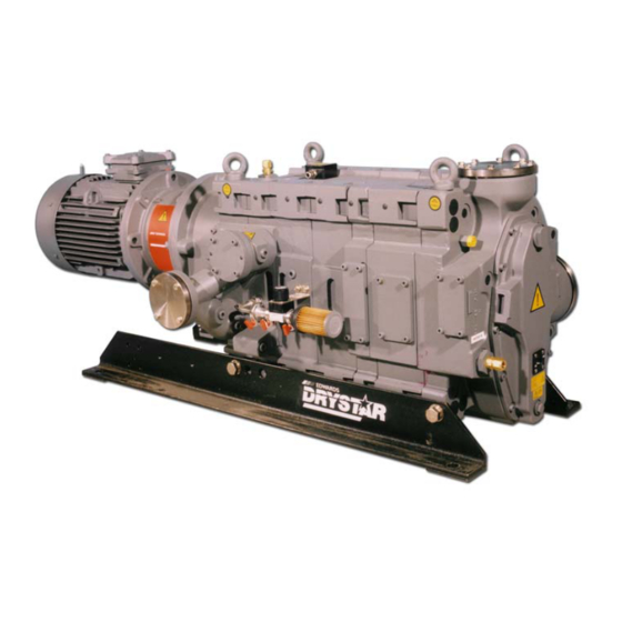
GV Dry Vacuum Pumps
Electrical Supply
380 - 415 V, 50 Hz
230 / 460 V, 60 Hz
380 - 415 V, 50 Hz
230 / 460 V, 60 Hz
380 - 415 V, 50 Hz
230 / 460 V, 60 Hz
50 Hz
60 Hz
50 Hz
60 Hz
A705-74-880
Issue K Original
Item Number
A705-71-900
A705-71-908
A705-73-900
A705-73-908
A705-74-900
A705-74-908
A705-74-985
A705-74-986
A705-75-985
A705-75-986
Advertisement
Table of Contents


Need help?
Do you have a question about the DRYSTAR GV Series and is the answer not in the manual?
Questions and answers