Table of Contents
Advertisement
Quick Links
Prodigyr HDLVr Pump
Generation II, Pump Manifold and
Circuit Board
Customer Product Manual
Part 1081195-11
Issued 10/18
For parts and technical support, call the
Finishing Customer Support Center at (800) 433-9319.
This document is subject to change without notice.
Check http://emanuals.nordson.com/finishing for the latest version
and available local languages.
NORDSON CORPORATION • AMHERST, OHIO • USA
Advertisement
Table of Contents
Troubleshooting

Related Manuals for Nordson Prodigy HDLV Pump Generation II


Summary of Contents for Nordson Prodigy HDLV Pump Generation II
- Page 1 Issued 10/18 For parts and technical support, call the Finishing Customer Support Center at (800) 433-9319. This document is subject to change without notice. Check http://emanuals.nordson.com/finishing for the latest version and available local languages. NORDSON CORPORATION • AMHERST, OHIO • USA...
-
Page 2: Table Of Contents
....... Contact Us Notice This is a Nordson Corporation publication which is protected by copyright. Nordson Corporation welcomes requests for information, comments, and Original copyright date 2007. No part of this document may be inquiries about its products. - Page 3 Replaced PCA replacement kit 1057815 with part number 1101498. 6/14 Replaced gasket part numbers. 1/16 Updated troubleshooting section. 3/16 Updated gaskets. 10/18 Updated gasket part numbers. Added enhanced pinch valve manifold kit. Added to torque instructions on assembling pump. Part 1081195-11 2018 Nordson Corporation...
- Page 4 Change Record Part 1081195-11 2018 Nordson Corporation...
-
Page 5: Safety
Any approvals documentation where appropriate. obtained for Nordson equipment will be voided if Make sure all equipment documentation, including instructions for installation, operation, and service these instructions, is accessible to all persons are not followed. -
Page 6: Fire Safety
Use only replacement parts that are designed cables, and wires after servicing equipment. for use with original equipment. Contact your Nordson representative for parts information and advice. Action in the Event of a Malfunction If a system or any equipment in a system... -
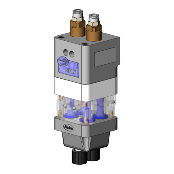
Page 7: Description
The standard-flow pump can be converted into a hi-flow pump by installing a hi-flow fluidizing tube retrofit kit. Refer to page 20 for the kit part number. The kit includes installation instructions. Figure 1 Prodigy HDLV Generation 2 Pump Part 1081195-11 2018 Nordson Corporation... -
Page 8: Hdlv Pump Components
Open and close to allow powder to be drawn in or dispensed out of the fluidizing tubes. Pinch Valve Manifold Houses the pinch valves. Made from clear plastic with metal thread inserts and ground spring molded in. Figure 2 HDLV Pump Components Part 1081195-11 2018 Nordson Corporation... -
Page 9: Theory Of Operation
As each half dispenses powder out, the powder in the tubing blends together, resulting in a consistent flow of powder from the spray gun. Powder Figure 4 Left Side Dispensing, Right Side Drawing In Part 1081195-11 2018 Nordson Corporation... -
Page 10: Purging
After the delivery side is purged, the delivery pinch valves close and the suction pinch valves open. Powder The suction side is purged in the same way as the delivery side. Figure 5 Purging Operation Part 1081195-11 2018 Nordson Corporation... -
Page 11: Specifications
Generator Powder Tubing Size 8 mm OD x 6 mm ID Output: 9−23 m (30−75 ft) Length Input: 1−3 m (3.5−12 ft) Dimensions 80.00 mm (3.150 in.) See Figure 6 Figure 6 Standard Pump Dimensions Part 1081195-11 2018 Nordson Corporation... -
Page 12: Powder Tubing Installation
4. Install the retaining nut over the end of the barbed adapter, then thread the nut onto the wear block and tighten it finger-tight. 5. Push the flexible powder tubing (5) over the barbed end of the adapter. Part 1081195-11 2018 Nordson Corporation... -
Page 13: Maintenance
Every Six Months use isopropyl alcohol to clean the adhesive from the manifold. Each Time You Lower Manifold Disassemble the Wear Blocks Pump Kit 1057260 Inspect the gasket for damage. Gasket Replace if necessary. 1613040 Part 1081195-11 2018 Nordson Corporation... -
Page 14: Troubleshooting
These troubleshooting procedures cover only the most common problems that you may encounter. If you cannot solve the problem with the information given here, call the Nordson Finishing Customer Support Center at (800) 433-9319 or contact your local Nordson representative for help. -
Page 15: Repair
Tighten Loosen the fluidizing the access plugs, then tube access plug and connect the purge air pull the fluidizing tube tubing. assembly straight out of the pump body. Retrofit Hi-Flow Part 1081195-11 2018 Nordson Corporation... -
Page 16: Pump Disassembly
Gaskets that are glued on do not need to be removed unless they are damaged. NOTE: Refer to Pinch Valve Replacement on page 16 for instructions on removing the pinch valves from the pinch valve manifold. Figure 9 Disassembly Preparation Part 1081195-11 2018 Nordson Corporation... - Page 17 21. Filter discs (4) 6. O-rings (4) 14. Lower manifold wear blocks (2) 22. Top manifold 7. Fluidizing tubes (2) 15. Lower manifold body 23. Screws M5 x 100 (3) 8. Body gasket 16. O-rings (2) Part 1081195-11 2018 Nordson Corporation...
-
Page 18: Pump Assembly
Y manifold. Once in contact with lower Y manifold, torque each screw to 20−25 in-lb. Refer to Pinch Valve Replacement Bottom on page 16 for specific instructions. Part 1081195-11 2018 Nordson Corporation... - Page 19 Tighten screws two turns at a time using an alternating pattern until pinch valve manifold contacts upper Y manifold. Once in contact with upper Y manifold, torque each screw to 20−25 in-lb. Part 1081195-11 2018 Nordson Corporation...
-
Page 20: Pinch Valve Replacement
UP flange of the pinch valve into the bottom end of the insertion tool. Align the pinch valve ribs with the square grooves in the valve chamber. Figure 13 Inserting Pinch Valve into Insertion Tool Part 1081195-11 2018 Nordson Corporation... - Page 21 Figure 15 Pulling Pinch Valve into Valve Manifold 4. Continue pulling on the insertion tool until the pinch valve pops through the valve manifold and the tool comes loose. Figure 17 Checking Rib and Groove Alignment Part 1081195-11 2018 Nordson Corporation...
-
Page 22: Parts
Prodigy HDLV Generation II Pump, Pump Manifold, and Circuit Board Parts To order parts, call the Nordson Finishing Customer Support Center at (800 433-9319 or contact your local Nordson representative. Pump Parts See Figure 18. Item Part Description Quantity Note —... - Page 23 Prodigy HDLV Generation II Pump, Pump Manifold, and Circuit Board Figure 18 Standard Pump Parts Part 1081195-11 2018 Nordson Corporation...
-
Page 24: Spare Parts
Retrofit Kit and four O-rings 1093596 installed) (Converts pump to hi-flow) Enhanced Pinch Valve Manifold Kit 1614438 (For parts included in kit, refer to Notes in parts list on page 18) Part 1081195-11 2018 Nordson Corporation... -
Page 25: Manifold And Circuit Board
NOTE: The circuit board provides control for up to two pump control manifolds. Figure 19 Prodigy HDLV Pump Control Manifold Note: Manifold solenoid wiring harness and circuit board not shown. Part 1081195-11 2018 Nordson Corporation... -
Page 26: Specifications
Tighten the pump mounting screws securely. 4. Tighten the manifold mounting screws securely. Figure 20 Pump and Manifold Installation 1. Mounting screws (2) 3. Pump panel wall 5. Manifold 2. Pump 4. Manifold mounting bracket 6. Manifold mounting screws (2) Part 1081195-11 2018 Nordson Corporation... - Page 27 Prodigy HDLV Generation II Pump, Pump Manifold, and Circuit Board This page intentionally left blank. Part 1081195-11 2018 Nordson Corporation...
-
Page 28: Circuit Board Installation
Purge Connector Suction 2 − Solenoid 4 CAN Out Connector Suction 1 − Solenoid 3 Pressure 1 − Solenoid 2 CAN In Connector Delivery 1 − Solenoid 1 CAN Network Termination Header Vacuum − Solenoid 7 Part 1081195-11 2018 Nordson Corporation... - Page 29 Bottom View Figure 21 Circuit Board Connections Note: The circuit board is shipped with air tubing labeled from 8−1 installed in the XDCR fittings. Connect the tubing to the appropriate fittings on the manifolds as illustrated. Part 1081195-11 2018 Nordson Corporation...
- Page 30 When you install a new circuit board, use this procedure to calibrate it to the manifold. Position 1 1. Turn off the Prodigy Manual Gun Controller. 2. Press and hold the Nordson key, then turn on 1 OPEN power to the Prodigy Manual Gun Controller. 2 OPEN The Configuration screen appears.
-
Page 31: Air And Powder Tubing Connections
Supply 3.45 bar (50 psi) Clear Pressure Transducer 10 mm 4 mm Pump 2 Flow Air Vacuum Generator Vent − Blue Clear Pressure Transducer Top of Manifold Bottom of Manifold Figure 26 Powder and Air Tubing Connections Part 1081195-11 2018 Nordson Corporation... -
Page 32: Operation
NOTE: When the fluidizing tubes become clogged with powder, the powder delivery rate will decrease. The gun controller will generate a fault to indicate this condition and notify you that it is time to replace the fluidizing tubes. Part 1081195-11 2018 Nordson Corporation... -
Page 33: Troubleshooting
This section contains troubleshooting procedures. These procedures cover only the most common problems that you may encounter. If you cannot solve the problem with the information given here, contact your local Nordson representative for help. Problem Possible Cause... - Page 34 Remove the nozzle, disassemble, and clean. Input air pressure too low Increase the input air pressure. Calibration constants incorrect Verify that the calibration constants on the manifold match what is entered in the manual spray gun controller. Continued... Part 1081195-11 2018 Nordson Corporation...
- Page 35 The delivery tubing must be arranged arrangement in a 3-ft. coil and be parallel to the ground. Delivery tubing length is not to The delivery tubing must be 60 ft. specification from the pump to the spray gun. Continued... Part 1081195-11 2018 Nordson Corporation...
- Page 36 If the discs are even slightly raised, the gasket will leak, causing the pump to malfunction. Pinch valve leaking Replace the pinch valves and filter disks. Lower Y-block plugged Remove and clean the lower Y-blocks. Continued... Part 1081195-11 2018 Nordson Corporation...
-
Page 37: A − Delivery Check
1. Clean or replace the delivery tubing. 2. Check the spray gun lock nut O-ring and replace it if it is missing or damaged. 3. Remove the nozzle and powder tubing adapter from the spray gun and clean or replace it. Part 1081195-11 2018 Nordson Corporation... -
Page 38: B − Suction Check
If no bubbles appear, check the short pieces of tubing connecting the manifolds and D2 pump valve and replace any that are worn out. Part 1081195-11 2018 Nordson Corporation... -
Page 39: Solenoid And Flow Control Valve Functions
Right Side Delivery Pinch Valve Left Side Fluidizing Tube Vacuum Air (on bottom of manifold) Left Side Suction Pinch Valve Pattern Air Flow Control Right Side Suction Pinch Valve Pump Air Flow Control Right Side Fluidizing Tube Part 1081195-11 2018 Nordson Corporation... -
Page 40: Repair
9. Install the coil on the stem, with the coil wiring to the mounting bracket. Take the manifold pointing away from the solenoid valves. Secure assembly to a clean work surface. the coil with the nut. Part 1081195-11 2018 Nordson Corporation... - Page 41 Manifold Repair 1. Nut 5. Spring 9. Orifice 2. Coil 6. Cartridge 10. Long screws (2) 3. Short screws (2) 7. Valve body 11. Screws (2) 4. Valve stem 8. O-rings (2) 12. Solenoid valve Part 1081195-11 2018 Nordson Corporation...
-
Page 42: Flow Control Valve Kit Replacement
The circuit board replacement kit comes with Refer to Installation on page 22 for instructions for detailed removal, installation, and calibration installing the manifold and pump into the pump instructions. Follow the instructions carefully to panel. avoid damaging the circuit board. Part 1081195-11 2018 Nordson Corporation... -
Page 43: Parts
Prodigy HDLV Generation II Pump, Pump Manifold, and Circuit Board Parts To order parts, call the Nordson Customer Support Center or your local Nordson representative. Manifold Parts See Figure 30. Item Part Description Quantity Note — 1101343 MANIFOLD ASSEMBLY, HDLV pump control,... - Page 44 Prodigy HDLV Generation II Pump, Pump Manifold, and Circuit Board Figure 30 Manifold Parts Part 1081195-11 2018 Nordson Corporation...
-
Page 45: Spare Parts
PCA Replacement Kit This kit comes with the 4-mm air tubing already installed into the pressure transducer fittings. Part Description Note 1101498 KIT, PCA replacement, Prodigy pump control, Generation III Figure 31 PCA Replacement Kit Part 1081195-11 2018 Nordson Corporation... -
Page 46: Air And Powder Tubing Part Numbers
6 mm Blue polyurethane 173101 8 mm Clear polyethylene − 900617 4 mm Clear polyurethane 900740 10 mm Blue polyurethane Top of Manifold Bottom of Manifold 1401537A Figure 32 Air and Powder Tubing Part Numbers Part 1081195-11 2018 Nordson Corporation... - Page 47 ATEX Quality Notification – Baseefa (2001) Ltd (UK) ___________________ Date: 12Feb2018 Vance Wilson Engineering Development Industrial Coating Systems Amherst, Ohio, USA Nordson Authorized Representative in the EU Contact: Operations Manager Industrial Coating Systems Nordson Deutschland GmbH Heinrich-Hertz-StraBe 42-44 D-40699 Erkrath Nordson Corporation ...
Need help?
Do you have a question about the Prodigy HDLV Pump Generation II and is the answer not in the manual?
Questions and answers