
Related Manuals for Vertiv eSure R48-3500e3


Summary of Contents for Vertiv eSure R48-3500e3
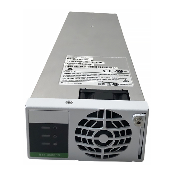
- Page 1 eSure™ Rectifier Module User Manual (UM1R483500e3), Revision H Specification Number: 1R483500e3 Model Number: R48-3500e3...
- Page 2 This document may contain confidential and/or proprietary information of Vertiv Group Corp., and its receipt or possession does not convey any right to reproduce, disclose its contents, or to manufacture or sell anything that it may describe. Reproduction, disclosure, or use without specific authorization from Vertiv Group Corp.
-
Page 3: Table Of Contents
Troubleshooting and Repair ................21 Troubleshooting ..............................21 Rectifier Current Sharing Imbalance ......................21 Rectifier Fault Symptoms and Troubleshooting ................21 Replacement Procedures ........................... 23 Rectifier Replacement ............................23 Rectifier Fan Replacement ..........................24 Vertiv | eSure™ Rectifier Module User Manual (UM1R483500e3) | Rev. H... -
Page 4: Admonishments Used In This Document
(ISO) SAFETY! Informs the reader of general safety information, reminders, precautions, or policies not related to a particular source of hazard or to fire safety. (ISO, ANSI, OSHA) Vertiv | eSure™ Rectifier Module User Manual (UM1R483500e3) | Rev. H... -
Page 5: Important Safety Instructions
ALERT! Installation or removal of equipment containing static sensitive components requires careful handling. Before handling any equipment containing static sensitive components, read and follow the instructions contained on the Static Warning Page. Vertiv | eSure™ Rectifier Module User Manual (UM1R483500e3) | Rev. H... -
Page 6: Static Warning
If necessary to repair equipment containing static sensitive components, wear an appropriately grounded wrist strap, work on a conductive surface, use a grounded soldering iron, and use grounded test equipment. Vertiv | eSure™ Rectifier Module User Manual (UM1R483500e3) | Rev. H... -
Page 7: Introduction
• Output Characteristics: Refer to Figure 1 for a graph of output voltage vs. output current. Figure 1: Output Voltage vs. Output Current Output voltage vs. Output current, Max. Output Power 3500W Output Current (A) Vertiv | eSure™ Rectifier Module User Manual (UM1R483500e3) | Rev. H... - Page 8 15 days in a year. (This refers to a total of 120 hours in any given year, but no more than 15 occurrences in that one- year period.) Vertiv | eSure™ Rectifier Module User Manual (UM1R483500e3) | Rev. H...
-
Page 9: Ac Input Ratings
≤5% from 50% to 100% of rated output current at 208 VAC, 220 VAC, 230 VAC, 240 VAC, 277 VAC for 50 Hz, 60 Hz, 53.5 VDC and 25 °C; ≤10% for 30% rated output current at 220 VAC, 50Hz, 53.5 VDC and 25 °C. Vertiv | eSure™ Rectifier Module User Manual (UM1R483500e3) | Rev. H... - Page 10 Maximum Input Current: Refer to Table 2. • Typical Input Data: 60 Hz input. Refer to Table Maximum Input Current: Refer to Table 4. • Efficiency Curve: Refer to Figure 4. Vertiv | eSure™ Rectifier Module User Manual (UM1R483500e3) | Rev. H...
- Page 11 Input Current Input Voltage Input Voltage (Amperes) 208/240 21.0 15.7 NOTE! At 100% of full load with output adjusted to 58 volts DC as measured at the shelf output terminals. Vertiv | eSure™ Rectifier Module User Manual (UM1R483500e3) | Rev. H...
- Page 12 Input Current Input Voltage Input Voltage (Amperes) 208/240 21.0 15.7 NOTE! At 100% of full load with output adjusted to 58 volts DC as measured at the shelf output terminals. Vertiv | eSure™ Rectifier Module User Manual (UM1R483500e3) | Rev. H...
-
Page 13: Environmental Ratings
NOTE! The rectifier is recommended to be used in an environment with Pollution of Degree 2 or less. Pollution Degree 2 applies where there is only non-conductive pollution that might temporarily become conductive due to occasional condensation (such as the office environment). Vertiv | eSure™ Rectifier Module User Manual (UM1R483500e3) | Rev. H... -
Page 14: Compliance Information
• Constant Current Mode: If load increases to the current limit setting, output voltage decreases linearly to maintain output current at the current limit setting. • Input Protection: AC Input Fuses F101, F102: AC 300 V, 30 A, fast acting, ceramic. Vertiv | eSure™ Rectifier Module User Manual (UM1R483500e3) | Rev. H... - Page 15 (by turning power to the rectifier off or by removing the rectifier, waiting until the LEDs on the rectifier extinguish, then turning power to the rectifier on or re-inserting the rectifier). Vertiv | eSure™ Rectifier Module User Manual (UM1R483500e3) | Rev. H...
- Page 16 The DSP also communicates with the controller in real time through the CAN bus. Table 5 lists the different commands and information exchanged between the rectifier and the controller. Vertiv | eSure™ Rectifier Module User Manual (UM1R483500e3) | Rev. H...
-
Page 17: Mechanical Specifications
Millimeters: 42.0 (Height) X 84.5 (Width) X 330 (Depth) Inches: 1.7 (Height) X 3.3 (Width) X 13.0 (Depth) • Weight: 1.7 kg (3.7 lbs) • Indicators: Power (Green) Protection (Yellow) Alarm (Red) Vertiv | eSure™ Rectifier Module User Manual (UM1R483500e3) | Rev. H... -
Page 18: Operation
Figure 5: Local Indicator Locations Power Indicator (Green) Protection Indicator (Yellow) Alarm Indicator (Red) R48-3500e3 Vertiv | eSure™ Rectifier Module User Manual (UM1R483500e3) | Rev. H... -
Page 19: Installing Rectifiers
WARNING! To prevent damage to the latching mechanism, ensure the handle is in the open position when installing or removing a rectifier. NEVER hold the handle in the closed position when installing a rectifier into a shelf. Vertiv | eSure™ Rectifier Module User Manual (UM1R483500e3) | Rev. H... - Page 20 Refer to “Rectifier Current Limit” on page 18 and the Power System documentation for instructions. Figure 6: Installing a Rectifier Latch Screw Handle Open the handle Vertiv | eSure™ Rectifier Module User Manual (UM1R483500e3) | Rev. H...
-
Page 21: Troubleshooting And Repair
• Power Indicator (Green) OFF • Protection Indicator (Yellow) ON • Protection Indicator (Yellow) Flashing • Alarm Indicator (Red) ON • Alarm Indicator (Red) Flashing Vertiv | eSure™ Rectifier Module User Manual (UM1R483500e3) | Rev. H... - Page 22 Rectifier addresses Replace the rectifier. contradictory. Alarm Fan not operating Indicator (rectifier shuts down). Replace the fan. (Red) Flashing Vertiv | eSure™ Rectifier Module User Manual (UM1R483500e3) | Rev. H...
-
Page 23: Replacement Procedures
Verify that the rectifiers are operating normally. Enable the external alarms, or notify appropriate personnel that this procedure is finished. Ensure that there are no local or remote alarms active on the system. Vertiv | eSure™ Rectifier Module User Manual (UM1R483500e3) | Rev. H... -
Page 24: Rectifier Fan Replacement
Reinstall the rectifier and again check for proper airflow. Enable the external alarms, or notify appropriate personnel that this procedure is finished. Ensure that there are no local or remote alarms active on the system. Vertiv | eSure™ Rectifier Module User Manual (UM1R483500e3) | Rev. H... - Page 25 Figure 7: Rectifier Fan Replacement Screw Faceplate Vertiv | eSure™ Rectifier Module User Manual (UM1R483500e3) | Rev. H...
- Page 26 Vertiv.com | Vertiv Headquarters, 1050 Dearborn Drive, Columbus, OH, 43085, USA UM1R483500e3 (RH 02/20)
Need help?
Do you have a question about the eSure R48-3500e3 and is the answer not in the manual?
Questions and answers