Sign In
Upload
Download
Table of Contents
Contents
Add to my manuals
Delete from my manuals
Share
URL of this page:
HTML Link:
Bookmark this page
Add
Manual will be automatically added to "My Manuals"
Print this page
×
Bookmark added
×
Added to my manuals
Manuals
Brands
Vertiv Manuals
Control Unit
R48-500
User manual
Vertiv R48-500 User Manual
Rectifier module
Hide thumbs
1
2
Table Of Contents
3
4
5
6
7
8
9
10
11
12
13
14
15
16
17
18
19
20
21
22
23
24
page
of
24
Go
/
24
Contents
Table of Contents
Troubleshooting
Bookmarks
Table of Contents
Table of Contents
Admonishments Used in this Document
Important Safety Instructions
Safety Admonishments Definitions
Safety and Regulatory Statements
Déclarations de Sécurité Et de Réglementation
Introduction
Overview
Specifications
Operation
AC Input Protection Device Requirements/Recommendations
Local Indicators
Rectifier High Voltage Shutdown and Lockout Restart
Installing Rectifiers
Troubleshooting and Repair
Troubleshooting
Replacement Procedures
Advertisement
Quick Links
Download this manual
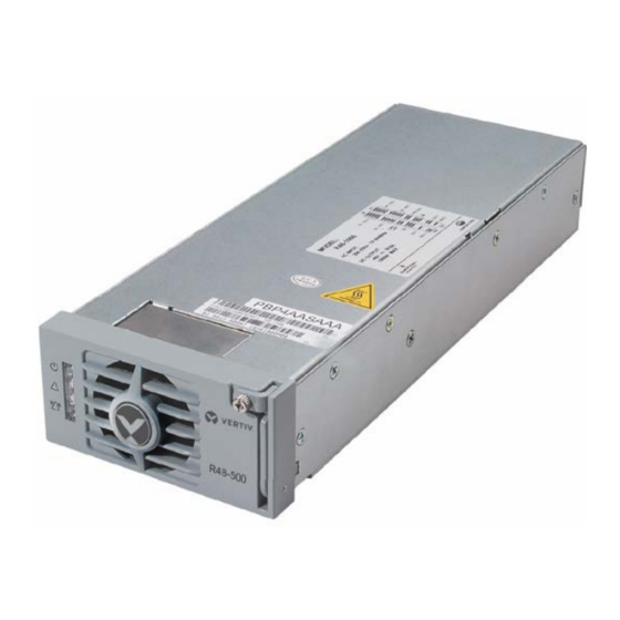
Rectifier Module
User Manual
Specification Number: 1R48500, 1R481000
Model Number: R48-500, R48-1000
Table of
Contents
Previous
Page
Next
Page
1
2
3
4
5
Advertisement
Table of Contents
Need help?
Do you have a question about the R48-500 and is the answer not in the manual?
Ask a question
Questions and answers
Related Manuals for Vertiv R48-500
Control Unit VERTIV NetSure Series User Manual
Rectifier module (32 pages)
Control Unit Vertiv NetSure R48-2000 User Manual
Rectifier module (32 pages)
Control Unit Vertiv eSure R48-3500e3 User Manual
Rectifier module (26 pages)
Control Unit Vertiv eSure R48-2000e3 User Manual
Rectifier module (26 pages)
Control Unit Vertiv R48-1000 User Manual
Rectifier module (24 pages)
Control Unit Vertiv eSure R48-1000e3 User Manual
Rectifier module (24 pages)
Control Unit Vertiv NetSure R48-4300E3 User Manual
Rectifier module (28 pages)
Control Unit Vertiv RPC2 Command Reference Manual
Communications module (52 pages)
Control Unit Vertiv NetSure R24-3000 User Manual
Rectifier module (24 pages)
Control Unit Vertiv Liebert IntelliSlot RDU101 Installer And User Manual
Communications card (60 pages)
Control Unit Vertiv Liebert CW Installer/User Manual
Thermal management system, 305 kw, 375 kw, 415 kw capacity, 50/60 hz (76 pages)
Control Unit Vertiv Liebert iCOM Installer/User Manual
Intelligent communication and monitoring for liebert mini-mate variable capacity 3 ton (184 pages)
Control Unit Vertiv Liebert SmartAisle2 User Manual
(130 pages)
Control Unit Vertiv Liebert MBSM User Manual
Multiple bus synchronization module (34 pages)
Control Unit Vertiv Liebert iCOM Installer/User Manual
Intelligent communication and monitoring for liebert crv (132 pages)
Control Unit Vertiv Netsure User Manual
(222 pages)
This manual is also suitable for:
R48-1000
1r48500
1r481000
Table of Contents
Print
Rename the bookmark
Delete bookmark?
Delete from my manuals?
Login
Sign In
OR
Sign in with Facebook
Sign in with Google
Upload manual
Upload from disk
Upload from URL


Need help?
Do you have a question about the R48-500 and is the answer not in the manual?
Questions and answers