
Related Manuals for rotork GT Series


Summary of Contents for rotork GT Series
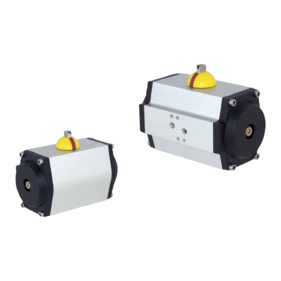
- Page 1 Range Pneumatic Actuator Single-Acting and Double-Acting Configuration Installation, Commissioning and Maintenance Manual Keeping the World Flowing...
-
Page 2: Table Of Contents
Rotork Fluid Systems reserves the right to modify, amend and improve this manual without notice. Installation, Commissioning and Maintenance Manual... -
Page 3: Introduction
For technical assistance, please contact the Rotork Fluid Systems Customer Service: E-mail: rfs.internationalservice@rotork.com Rotork Fluid Systems, Via Padre Jaques Hamel 138B, Porcari, Lucca, IT. Tel: +39 0583-222-1 Rotork plc, Brassmill Lane, Bath, UK. Tel +44 (0)1225 733200 Keeping the World Flowing... -
Page 4: General Information
This manual is produced to enable a competent user to install, Before installing the equipment, verify it is suitable for the operate and maintain the Rotork Fluid Systems GT Actuator intended application. If unsure consult Rotork Fluid Systems. Single- and Double-Acting. -
Page 5: Magnetic Risks
Do not disassemble the actuator In case of ATEX and/or EAC certifications the following labels during dismantling. Follow instructions with be also applied: in the manual and contact Rotork Fluid Systems. Fluid Systems MODEL: GT / RCR - PNEUMATIC ACTUATOR... -
Page 6: Operating Limits
Operating Limits Tightening Torque Chart Temperature: -50 °C to +70 °C (-58 °F to +158 °F) NBR o-ring, Delrin Guide Screw Torque Stop nut -15 °C to +160 °C (+5 °F to +320 °F) Actuator size size (Nm) (Nm) Viton o-ring, IXEF Guide 52 - 63 -60 °C to +200 °C (-76 °F to +352 °F) Silicon o-ring, PTFE Guide... -
Page 7: Handling & Lifting
Handling & Lifting Only trained and experienced personnel should handle/lift the actuator. GT actuators are supplied packed in cardboard boxes suitable for normal handling. Handle the actuator with care. Lifting Recommendations • The lifting device and the sling must be suitably rated for the actuator weight and dimensions •... -
Page 8: Storage
Storage Long Term Storage Rotork Fluid Systems actuators have been fully tested before If long term storage is necessary, further operations must leaving the factory. be carried out to maintain the actuator in a good working condition: In order to keep the actuator in good condition until installation, at least the following measures are •... -
Page 9: Installation On Valve
(refer to PUB110-001 for metric and PUB110-002 for operating drawings and TAG numbers. imperial) Consult Rotork Fluid Systems for any additional information. • Actuator is supplied in the fail position (for single-acting). Set the valve in the right position according to the 10.1 Preliminary Actions... -
Page 10: Assembly Configurations
Removal shall be performed only by qualified staff, wearing/using appropriate personal protection devices. Do not remove the actuator if the valve is blocked in the intermediate position. Contact Rotork Fluid Systems Customer Service. In order to disassemble the actuator from the valve, proceed as follows: •... -
Page 11: Operation
The following instructions must be followed and integrated into end user safety program when installing and using Rotork products. Read and save all instructions prior to installing, operating and servicing this product. Follow all warnings, cautions and instructions marked on and supplied with the product. -
Page 12: Single And Double Limit Stop
12.0 Operation 12.2 Single and Double Limit Stop GT Actuators can be provided in 2 versions: single and double limit stop. The single limit stop is provided with 2 identical mechanical stop bolts installed in the end caps and allows adjustment of the open stroke of a clockwise to close (close stroke of an anti-clockwise to close) actuator. -
Page 13: Angular Stroke Setting
12.0 Operation 12.3 Angular Stroke Setting Single and double-acting actuator, cylinder stop bolt setting Perform the following operations as first setting. Adjust the stop bolt located in the end flange of the cylinder as follows: E. Hold the stop bolt (2) with a Allen (hex.) key and carefully tighten the stop nut (1) G: Repeat the operation for the other stop bolt A. -
Page 14: Pneumatic Power Supply
12.0 Operation 12.4 Pneumatic Supply Verify allowed supply pressure range on actuator label. Verify medium composition. Contact Rotork Fluid Port 4 Systems to check the compatibility with the supply medium. Port 2 12.5 Pneumatic Connections Preliminary Operations A. Verify sizes of pipes and fittings according to applicable plant specifications B. -
Page 15: Electrical Connections
12.0 Operation 12.6 Electrical Connections 12.7 Start Up During start-up of the actuator, it is necessary to check if: Check electrical component supply voltage, before start-up. • Medium supply pressure is as prescribed • The power supply to electrical components (solenoid Access to live electrical conductors is forbidden in valves coils, limit switches, pressure switches, etc.) are hazardous areas unless done under a special permit. -
Page 16: Dismantling & Disposal
Should you require technical assistance or spares, Rotork guarantees For Single-Acting Actuator the best service in the world. Contact your local Rotork representative or the factory direct at the address on the The spring cartridge module contains potential nameplate, quoting the actuator type and serial number. -
Page 17: Troubleshooting
Loss of power pressure exceeds the required valve torque • Replace seals according instructions reported in • Leakage from cylinder PM-GT-005/006 For other problems, please contact Rotork Fluid Systems Customer Service. Keeping the World Flowing... -
Page 18: Periodic Maintenance
16.0 Periodic Maintenance Rotork Fluid Systems recommends performing the following checks to help comply with the rules and regulations of the country of final installation: Remove pressure before proceeding with maintenance operations, discharge any accumulators or tanks (if present), except where otherwise indicated. - Page 19 16.0 Periodic Maintenance PM-GT-001 Page:1/1 Component: Single-Acting actuator Task: Cleaning Double-Acting actuator Equipment, Tools, Materials: Warnings: Damp cloth Project documentation (design and operating pressure values) Preliminary Operations: Description: Remove electric and pneumatic supply before proceeding. 1. Remove dust from actuator external surface with a damp cloth The tools and cleaning procedures must not produce sparks or create adverse conditions in the environment during maintenance operations, so as to prevent potential explosion hazards.
- Page 20 16.0 Periodic Maintenance PM-GT-002 Page:1/1 Component: Single-Acting actuator Task: Functional test Double-Acting actuator Equipment, Tools, Materials: Warnings: Chronometer/timer Project documentation (required stroke times) Preliminary Operations: Description: NOTE: Actuator must be connected to the pneumatic supply to perform the following test. 1.
- Page 21 16.0 Periodic Maintenance PM-GT-004 Page:1/1 Component: Electrical components (if present) Task: Check electrical components (if present) and grounding connections Equipment, Tools, Materials: Warnings: Project documentation Preliminary Operations: Description: Isolate electrical power supply before working on electrical devices. Read and follow the safety precautions reported in the Manufacturer’s Maintenance Manual. Risk of temporary modification of the component protection.
- Page 22 16.0 Periodic Maintenance PM-GT-005 Page:1/2 Component: Single limit stop actuator pneumatic cylinder seals Task: Pneumatic cylinder seals replacement replacement (Spring-Return and Double-Acting Actuator) Equipment, Tools, Materials: Warnings: Spare seals Wrench Lifting tools Project documentation Preliminary Operations: Removal from Valve Description: Note: the following instructions apply both to Single-Acting and Double-Acting actuators unless otherwise specified.
- Page 23 16.0 Periodic Maintenance PM-GT-005 Page:2/2 Component: Single limit stop actuator pneumatic cylinder seals Task: Pneumatic cylinder seals replacement replacement (Spring-Return and Double-Acting Actuator) Equipment, Tools, Materials: Warnings: Spare seals Wrench Lifting tools Project documentation Preliminary Operations: Removal from Valve 11. Remove o-ring (7) and guide belt (8) 12.
- Page 24 16.0 Periodic Maintenance PM-GT-006 Page:1/4 Component: Double limit stop actuator pneumatic cylinder seals Task: Pneumatic cylinder seals replacement replacement (Spring-Return and Double-Acting Actuator) Equipment, Tools, Materials: Warnings: Spare seals Wrench Lifting tools Project documentation Preliminary Operations: Removal from Valve Description: Note: the following instructions apply both to Single-Acting and Double-Acting actuators unless otherwise specified.
- Page 25 16.0 Periodic Maintenance PM-GT-006 Page:2/4 Component: Double limit stop actuator pneumatic cylinder seals Task: Pneumatic cylinder seals replacement replacement (Spring-Return and Double-Acting Actuator) Equipment, Tools, Materials: Warnings: Spare seals Wrench Lifting tools Project documentation Preliminary Operations: Removal from Valve 11. Loosen the nut (10) with a socket wrench, remove washer (12) and o-ring (11) 12.
- Page 26 16.0 Periodic Maintenance PM-GT-006 Page:3/4 Component: Double limit stop actuator pneumatic cylinder seals Task: Pneumatic cylinder seals replacement replacement (Spring-Return and Double-Acting Actuator) Equipment, Tools, Materials: Warnings: Spare seals Wrench Lifting tools Project documentation Preliminary Operations: Removal from Valve 16. Remove o-ring (7) and guide belt (8) 17.
- Page 27 16.0 Periodic Maintenance PM-GT-006 Page:4/4 Component: Double limit stop actuator pneumatic cylinder seals Task: Pneumatic cylinder seals replacement replacement (Spring-Return and Double-Acting Actuator) Equipment, Tools, Materials: Warnings: Spare seals Wrench Lifting tools Project documentation Preliminary Operations: Removal from Valve 28. Reinstall (3) springs, if present 29.
- Page 28 16.0 Periodic Maintenance CM-GT-001 Page:1/1 Component: Single limit stop Spring-Return and Double-Acting actuator Task: Fail mode converting Equipment, Tools, Materials: Warnings: Wrench Lifting tools Project documentation Preliminary Operations: Removal from Valve 1. With an Allen (hex.) key remove the 4 screws (1) from the end cap (2) 2.
- Page 29 16.0 Periodic Maintenance CM-GT-002 Page:1/3 Component: Double limit stop Spring-Return and Double-Acting Task: Fail mode converting actuator Equipment, Tools, Materials: Warnings: Wrench Lifting tools Project documentation Preliminary Operations: Removal from Valve 1. With an Allen (hex.) key remove the 4 screws (1) from the end cap (2) 2.
- Page 30 16.0 Periodic Maintenance CM-GT-002 Page:2/3 Component: Double limit stop Spring-Return and Double-Acting Task: Fail mode converting actuator Equipment, Tools, Materials: Warnings: Wrench Lifting tools Project documentation Preliminary Operations: Removal from Valve 7. Remove the end cap (2) 8. Remove the springs (3), if present 9.
- Page 31 16.0 Periodic Maintenance CM-GT-002 Page:3/3 Component: Double limit stop Spring-Return and Double-Acting Task: Fail mode converting actuator Equipment, Tools, Materials: Warnings: Wrench Lifting tools Project documentation Preliminary Operations: Removal from Valve 12. Reinstall (3) springs, if present 13. Reinstall end cap (2) and tighten screws (1) – refer to section 6.3 14.
-
Page 32: Part List
17.0 Part List Single Stop Actuator Fig 17.1 Single Stop Actuator ITEM DESCRIPTION ITEM DESCRIPTION Piston guide belt Spring cartridge ● Pinion upper washer Circlip Pinion upper bearing Pinion bottom washer Stop bolt o-ring ● Piston sliding guide Upper pinion o-ring ●... - Page 33 17.0 Part List Double Stop Actuator Fig 17.2 Double Stop Actuator ITEM DESCRIPTION ITEM DESCRIPTION Piston Guide Belt Body end caps ● Pinion upper washer Spring cartridge Model dependant Pinion upper bearing Circlip Guiding bush Pinion bottom washer Stop bolt o-ring ●...
-
Page 34: Grease Specification
In general, there is no need to lubricate the actuator because its mechanism is lubricated for life. The standard grease for Rotork Fluid Systems GT actuators is shown below. If an alternative was specified and/or supplied, please refer to the job specific documentation. - Page 35 Keeping the World Flowing...
- Page 36 +44 (0)1225 733200 +44 (0)1225 333467 email mail@rotork.com All Rotork Fluid Systems actuators are manufactured under a third party accredited ISO9001 quality assurance programme. As we are continually developing our products, their design is subject to change without notice. PUB110-009-00 The name Rotork is a registered trademark.
Need help?
Do you have a question about the GT Series and is the answer not in the manual?
Questions and answers