rotork IQ3 Instructions For Safe Use, Installation, Basic Setup And Maintenance
Hide thumbs
Also See for IQ3:
- Safe use and installation manual (16 pages) ,
- Instructions for safe use, installation, and maintenance (8 pages)
Table of Contents
Advertisement
Advertisement
Table of Contents

Related Manuals for rotork IQ3


Summary of Contents for rotork IQ3
- Page 1 IQ Range Instructions for Safe Use, Installation, Basic Setup and Maintenance This manual contains important safety information. Please ensure it is thoroughly read and understood before installing, operating or maintaining the equipment. PUB002-039-00 Date of issue 03/18...
-
Page 2: Table Of Contents
6.1 Rising Stem Valves Top Mounted ... . 15 1.2 Rotork Setting Tool ..... . . 4 6.2 Valve with Gearbox –... -
Page 3: Introduction
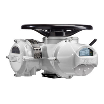
Hand / Auto lever Hand wheel Name plate Display window Oil plug Control Cover Oil plug Terminal Cover Conduit entries Local / Remote / Stop Oil plug Motor selector Base Open / Close selector IQ3 manual – Section: Introduction... -
Page 4: Rotork Setting Tool
2. The following checks must be conducted applicable code of practice. The new BTST is able to connect to Rotork USA – FM Int Safe Class I, Div 1, Groups A, on the BTST prior to taking it into a Bluetooth ®... -
Page 5: Introduction To This Manual
It should only be installed in hazardous of the Rotork IQ range of actuators be area locations compatible with the Visit our web site at www.rotork.com required, it will be provided on request. - Page 6 Rotork electric actuators, refer to the hazardous area certification will section 4.1. be invalidated. Additional electrical hazards may occur when using this configuration. The user should ensure that any necessary additional safety measures are considered. IQ3 manual – Section: Health and Safety...
-
Page 7: Atex/Iec Ex Certified Actuators
Rotork. covers are removed. Every Rotork actuator has been fully tested before leaving the factory to give years of trouble free operation, providing it is correctly commissioned, installed and sealed. -
Page 8: Operating Your Iq Actuator
Remote Control Rotate the red selector to the Remote position (clockwise), this allows remote control signals to operate the actuator. Local Stop can still be used by turning the red knob anti-clockwise. IQ3 manual – Section: Operating your IQ Actuator... -
Page 9: Display - Local Indication
Positioning (% position / demand) to 1 decimal place. communication activity. LEDs will also homescreens are selected. Refer to flash when keys are pressed. section 4.4. IQ3 manual – Section: Operating your IQ Actuator... -
Page 10: Display - Home Screen Selection
5 minutes after the Positioner - Position with digital and last setting tool command or until the analogue position demand indication actuator power is cycled. IQ3 manual – Section: Operating your IQ Actuator... -
Page 11: Display Status Indication - Travel
After replacing a battery the alarm icon will continue to be displayed Fig. 4.7.1 until the next check and may take up to 1 hour. Cycling the power will force a battery check and clear the alarm. IQ3 manual – Section: Operating your IQ Actuator... -
Page 12: Preparing The Drive Bush
O-rings Fig. 5.1.2 F10 base assembly Fig. 5.1.3 F14 & F16 base assembly from the drive bush prior to machining may result in damage to the bearing. Fig. 5.1.1 IQ3 manual – Section: Preparing the Drive Bush... -
Page 13: Non-Thrust Base Type B
F25 / FA25 Base — 8 off / M12 cap head screws: 89 Nm / 65 lbs.ft F30 / FA30 Base — 10 off / M16 cap head screws: 218 Nm / 160 lbs.ft Fig. 5.2.2 IQ3 manual – Section: Preparing the Drive Bush... -
Page 14: Mounting The Actuator
ISO 5210 or USA Standard MSS SP101 must be fitted to the valve. Actuator to valve fixing must confirm to Material specification ISO Class 8.8, yield strength 628 N/mm Fig. 6.2.2 IQ3 manual – Section: Mounting the Actuator... -
Page 15: Rising Stem Valves Top Mounted
736.8 543.4 actuator until the drive dogs on the actuator output shaft engage into the Fig. 6.1.3 Table B drive bush. Actuator flange should now be flush with the base. IQ3 manual – Section: Mounting the Actuator... -
Page 16: Handwheel Sealing
Commissioning of the IQM range is identical to the standard IQ - refer to Fig. 6.6.2 IQML without Yoke Section 8. Fig. 6.4.1 Fig. 6.6.1 IQML with Yoke Fig. 6.4.2 IQ3 manual – Section: Mounting the Actuator... -
Page 17: Iql & Iqml Adjusting Linear Stroke
Fig. 6.7.1 Turn the actuator handwheel clockwise, the linear drive will move Fig. 7.1.1 Terminal numbers refer to connections as shown on the actuator circuit diagram down towards the valve spindle and IQ3 manual – Section: Cable Connections... -
Page 18: Earth/Ground Connections
WARNING: Actuators for use on phase to phase voltages greater than 600 V must not be used on supply systems such as floating, or earth-phase systems, where phase to earth voltages in excess of 600 VAC could exist. IQ3 manual – Section: Cable Connections... - Page 19 ACHTUNG: DIE ROTEN PLASTIKSTOPFEN SIND NUR FÜR DEN TRANSPORT GEEIGNET. FÜR DAVERHAFTEN SCHUTZ SIND DIESE GEGEN GEEIGNETE BLINDSTOPFEN AUSZÜTAUSCHEN. ATTENTION: LES BOUCHONS PLASTIQUES ASSURENT UNE PROTECTION TEMPORAIRE. POUR UNE PROTECTION DEFINITIVE UTILISER DES BOUCHONS METALLIQUES. IQ3 manual – Section: Cable Connections...
-
Page 20: Cable Entry
Fig. 7.4.1 hazardous' live circuits considering, and in accordance with, national regulations and statutory provisions. Tags are secured with the supplied 4 mm (control and indication) and 5 mm (power) pan head screws. Fig. 7.4.2 IQ3 manual – Section: Cable Connections... -
Page 21: Replacing Terminal Cover
1 off AMP ring tag 34148 greased before refitting cover. If the actuator has been supplied with per terminal when required. the valve, the valvemaker or supplier may have already made these settings. IQ3 manual – Section: Commissioning - Basic Settings... -
Page 22: Connecting To The Actuator
Bluetooth connection will be turned off and the Setting tool and display blue lights will go out. To manually turn off Bluetooth connection at any time, Back Forward Down press the setting tool keys together. Fig. 8.1.1 IQ3 manual – Section: Commissioning - Basic Settings... -
Page 23: Security - Password
Press the key. Fig. 8.2.1 Select OK to return to settings screen. IQ3 manual – Section: Commissioning - Basic Settings... -
Page 24: Basic Settings Menu
TORQUE SWITCH the actuator. Other functions can BYPASS be set as required. Security Close Closing Position (100 - 5%) Open Open Position (0 - 95%) Defaults IQ3 manual – Section: Commissioning - Basic Settings... -
Page 25: Basic Settings - Limits
CL. Bypass Pos 15 / 15 1 / 15 Function Close Direction (1 / 15) is shown highlighted. Use to scroll through functions. Functions will be highlighted in turn. Blank settings are IQT only. IQ3 manual – Section: Commissioning - Basic Settings... -
Page 26: Close Settings
Move the actuator and valve to the required setting. Press to set. close position. Allow for overrun by winding in the opening direction by ½ to 1 turn. Press to set the close limit position. IQ3 manual – Section: Commissioning - Basic Settings... -
Page 27: Torque Switch Bypass
% open. Note: Turns and Position values do not update while being displayed on screen. To see updated values, key to return to Settings Menu, then select Limits. IQ3 manual – Section: Commissioning - Basic Settings... -
Page 28: Maintenance, Monitoring And Troubleshooting
The battery is not required to retain except replacement of the battery. should be replaced to ensure correct any actuator settings or track position Electrical supplies must be isolated before power off valve position indication. changes. IQ3 manual – Section: Maintenance, Monitoring and Troubleshooting... - Page 29 ATEX/IEC Ex - Rotork Part 95-462 or Low/High Temp Numbers: 95-614 the torque developed through stroke Fig. 9.7.2 Battery Type Table IQ3 manual – Section: Maintenance, Monitoring and Troubleshooting...
-
Page 30: Environmental
13 02 08 waste disposal companies Grease Side Handwheel / linear drive 13 02 08 May require special treatment before Rubber Seals & O-rings Cover and shaft sealing 16 01 99 disposal, use specialist waste disposal companies IQ3 manual – Section: Environmental... -
Page 31: Weights And Measures
IQL and IQML linear drive assemblies *Oil capacity shown for Top Hand should be regularly lubricated using Wheel actuators. Side Hand Wheel extreme pressure multi-purpose grease actuator capacity is 2.20 (4.65). MULTIS MS2 or equivalent. IQ3 manual – Section: Weights and Measures... -
Page 32: Iq Approvals
Ex tb IIIC T120°C Db, IP66 & IP68 Temperature -20°C to +70°C (-4°F to +158°F) *Option -30°C to +70°C (-22°F to +158°F) *Option -40°C to +70°C (-40°F to +158°F) *Option -50°C to +40°C (-58°F to +104°F) IQ3 manual – Section: IQ Approvals... - Page 33 Temperature -30°C to +70°C (-22°F to +158°F) *Option -40°C to +70°C (-40°F to +158°F) *Option -40°C to +70°C (-40°F to +158°F) *Option -50°C to +70°C (-58°F to +158°F) *Option -50°C to +40°C (-58°F to +104°F). IQ3 manual – Section: IQ Approvals...
-
Page 34: Approved Fuses
1 to 50 Hz Seismic if it is to operate during and after the event Independent tests have shown Emitted noise that at 1m generated noise does not exceed 65 db(A) IQ3 manual – Section: Approved Fuses... -
Page 35: Maximum Constructional Flamepath Gaps For Atex And Iecex Approved Actuators
DC Motor Adaptor / Gearcase 0.15 25.00 IQD10, IQD12, IQD18, IQD20, IQD25 DC Motor Cover / DC Motor Cover Adaptor 0.15 12.50 IQD10, IQD12, IQD18, IQD20, IQD25 Note: Negative sign denotes an interference fit. IQ3 manual – Section: Conditions of Safe Use... - Page 36 The name Rotork is a registered trademark. Rotork recognises all registered trademarks. The Bluetooth ® word mark and logos are registered trademarks owned by Bluetooth SIG, Inc. and any use of such marks by Rotork is under license. Published and produced in the UK by Rotork Controls Limited. Date of issue 03/18 POWTG0918...
Need help?
Do you have a question about the IQ3 and is the answer not in the manual?
Questions and answers