
Related Manuals for rotork centork CK Series


Summary of Contents for rotork centork CK Series
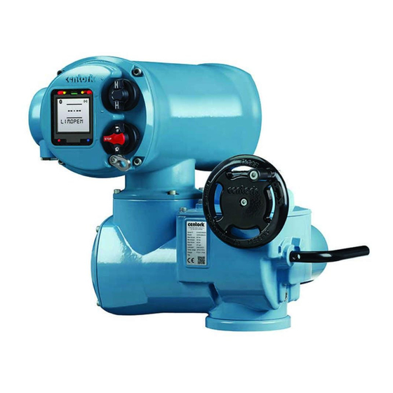
- Page 1 Brand & CK - Centronik Start Up Guide Modular Design Electric Valve Actuators...
-
Page 2: Table Of Contents
Contents CK - Valve Actuation Centronik Interface Using the product and CK - Centronik Quick Start Guide Basic Settings - Local Controls Basic Settings - Setting Tool Basic Settings - Digital Switch Mechanism Basic Settings - Mechanical Switch Mechanism CK Additional Indication Drive Basic Settings CK –... -
Page 3: Ck C And Ck Rc - Centronik Quick Start Guide
and CK - Centronik Quick Start Guide Centronik Controls A IrCK Transmitter / Receiver Open Close D Remote Stop Local OPEN LIM DEMO Centronik Interface A Bluetooth Connection Infrared Connection IrCK Configuration Mode D Communication Feedback Valve Position SETTINGS Current Menu LIMITS G Sub Menu / Setting Value Brand... - Page 4 Centronik Interface – Using the product The Centronik Control Module can be configured using 2 different Alternatively the local selector knobs can be used to navigate input methods. An optional Bluetooth Setting Tool provides a in the same way. Be sure to read and understand the equivalent handheld solution compatible with Infrared or optional Bluetooth input commands.
-
Page 5: Centronik Interface
Centronik Interface – Using the product Interface Feedback The Centronik display interface includes various features that provide feedback to the operator. This ensures that changes to the configuration of the actuator can be confirmed and validated during the commissioning process. Arrow Identification During general menu navigation, each submenu/setting will have a set of behaviour arrows associated with it. -
Page 6: Basic Settings - Local Controls
PUB111-005. The arrow behaviour will indicate the setting value is in edit mode and blank spaces will also be filled (see Fig. 2). Fig. 2 Default password shown in edit mode. Confirm ROTORK as the password by inputting... -
Page 7: Basic Settings - Setting Tool
Centronik Interface - Basic Settings - Setting Tool Entering Configuration mode To access configuration mode with the Bluetooth Setting Tool, ensure the actuator is in Local or Stop mode and point the setting tool directly at the IrCK LED. Press to initiate communication. -
Page 8: Basic Settings - Digital Switch Mechanism
Centronik Interface - Basic Settings - Digital Switch Mechanism The menu map below provides direction for the basic setting and commissioning of a CK or CK actuator equipped with a Digital Switch Mechanism and Centronik Control Module. USER X MAIN.MENU LANGUAGE SETTINGS LIMITS... - Page 9 Centronik Interface - Basic Settings - Digital Switch Mechanism Main Menu > Settings > Limits Limits > Open Settings [OPEN.SETT.] Action [ACTION] The Limits menu details all of the appropriate settings to control the conditions for stopping actuator movement. Press to edit, select preferred option using for Seat Use the menu map on the previous page to follow the menu...
- Page 10 Centronik Interface - Basic Settings - Digital Switch Mechanism Limits > Torque Limit Bypass [TRQ.LIM.B.P.] Torque Limit Bypass Position [OP.BP.POSI.] Occasionally applications will require a break to open or break to value dictates the travel away from the closed close torque that exceeds the standard torque limit. Setting the position limit that the torque limit will be bypassed in the open torque limit bypass will ignore existing torque limit settings and direction.
-
Page 11: Basic Settings - Mechanical Switch Mechanism
Centronik Interface - Basic Settings - Mechanical Switch Mechanism Test Feedback Switches 1) Confirm the torque or limit switches are functional by monitoring feedback on the Centronik display during switch testing. The main power supply must be maintained during this test procedure to ensure feedback via the Centronik display. - Page 12 Centronik Interface - Basic Settings - Mechanical Switch Mechanism Test Feedback Switches 3) Test torque switches in both directions using a flat screwdriver to turn TS TEST (ACW for open, CW for close). Feedback that the switch state has changed will be seen on the Centronik display interface.
- Page 13 Centronik Interface - Basic Settings - Mechanical Switch Mechanism A 5mm Allen (Hex.) key and 0.8 x 4mm flat screwdriver are required to perform commissioning of the CK Mechanical Switch Mechanism. Set torque limits A Indicator/Adjustment Point Torque Cam Clutch Screw 1) Move the valve to a mid-travel position and loosen the Torque Cam Clutch 1.5 turns using a flat screwdriver.
- Page 14 Centronik Interface - Basic Settings - Mechanical Switch Mechanism Open Torque Adjustment Point D Close Torque Adjustment Point 3) Tighten the Torque Cam Clutch Screw once both torque trip limits have been set. CAUTION: Ensure the Torque Cam Clutch Screw is tightened enough to fully deform the spring washer underneath the screw head.
- Page 15 Centronik Interface - Basic Settings - Mechanical Switch Mechanism Set Position Limits OLS Indicator Window G OLS Adjustment Screw H Drive Clutch Shaft CLS Indicator Window CLS Adjustment Screw 1) Move actuator to the valve CLOSED position using handwheel operation. 2) Using a flat screwdriver, depress the Drive Clutch Shaft and rotate to “Run”...
- Page 16 Centronik Interface - Basic Settings - Mechanical Switch Mechanism 8) Move actuator to the valve OPEN position using handwheel operation. 9) Using a flat screwdriver, depress the Drive Clutch Shaft and rotate to “Set” position as shown on the switch mechanism faceplate. 10) The OLS Adjustment Screw must now be rotated to make the open limit switch inside the switch mechanism.
- Page 17 Centronik Interface - Basic Settings - Mechanical Switch Mechanism For CK or CK actuators fitted with a Mechanical Switch Mechanism, the required end of travel action (torque or position) [ACTION] is determined by the setting within the Centronik configuration. All other limit functions will not be available as they need to be intrusively set on the mechanism.
-
Page 18: Ck Additional Indication Drive Basic Settings
CK Additional Indication Drive - Basic Settings Test Feedback Switches 1) Confirm the torque or limit switches are functional by monitoring feedback on the Centronik display during switch testing. The main power supply must be maintained during this test procedure to ensure feedback via the Centronik display. - Page 19 CK Additional Indication Drive - Basic Settings Test Feedback Switches 3) Test torque switches in both directions using the TS TEST lever shown on the left side of the unit between the AID module and Mechanical Switch Mechanism (move DOWN for open, UP for close).
- Page 20 CK Additional Indication Drive – Basic Settings Setting Local Position Disc The AID module includes a Local Position Disc that should be configured to show Open and Close limit positions. A series of reduction gears ensure a suitable range of travel can be accommodated.
- Page 21 CK Additional Indication Drive – Basic Settings 6) Move the actuator to the OPEN limit using electrical or operation or the handwheel. 7) Loosen off the Position Disc Retaining Screw by 1 turn whilst holding the CLOSE portion of the Position Disc. 8) Rotate only the red OPEN portion of the disc so that OPEN reads horizontally and then hold both portions in place.
- Page 22 CK Additional Indication Drive – Basic Settings Setting Intermediate Switches The AID Module can include four additional switches to indicate configurable intermediate positions. CAUTION: The actuator position limits must be configured prior to setting the Intermediate Switches. 1) Move the actuator to the desired intermediate position using electrical operation or the handwheel.
- Page 23 CK Additional Indication Drive – Basic Settings Setting the POT The AID Module can include a potentiometer to report intermediate position to the Centronik control module. This can also be used in parallel to a digital switch mechanism to provide a direct potentiometric output or a loop powered 4-20 mA scaled CPT (Current Position Transmitter) option.
- Page 24 Spain +1 585 247 2304 +34 943 316137 PUB111-004-00 +1 585 247 2308 +34 943 223657 Brand Issue 08/16 USASales@centork.com email email Sales@centork.com www.centork.com As part of a process of on-going product development, Centork reserves the right to amend and change specifications without prior notice. Published data may be subject to change.
Need help?
Do you have a question about the centork CK Series and is the answer not in the manual?
Questions and answers
Elektrik bağlantısı klemes şeması yollarmisiniz